


DLQ-3000+
Rev. A
2-32
Front paper sensor
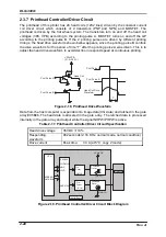
Front paper sensor detects TOF position as well as paper presence condition. It uses a
photo interrupter system. However, one end of the detecting lever is mechanically used
to detect the leading edge of the paper, and the other end is to cut in between the photo
interrupter sensor to detect paper. The output signal is pulled up to 10 K
Ω
, then input to
the CPU port via the filter circuit which consists of the resistor and the condenser.
Table 2-24. Front Paper Sensor Specification
Detecting method
Photo interrupter systems
Output system
Open collector system
Resistance to voltage:30V or less
Sink current : 0.3 mA or less
Detecting mode
Paper detected : LOW
No paper detected : HIGH
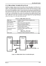
Right/left PEW sensor
Right/left sensors are located on the left and right column direction with the CR on the
mask guide in between. They don’t only detect paper but the paper width so as to
determine the right and left margins. The output signal is output to the CPU A/D
converter.
Table 2-25. Right/left PEW Sensor Specification
Detecting method
Photo micro sensor system
Output system
Collector
Power supply voltage
5 VDC
±
5%
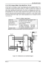
CR home position sensor
The output signal for this sensor is pulled up to 10K
Ω
, then input to the CPU A/D
converter via the filter circuit which consists of the resistor and the condenser.
Table 2-26. CR Home Position Sensor Specification
Detecting method
Photo coupler system
Output system
Open collector system
Resistance to voltage:30V or less
Sink current : 0.3 mA or less
Power supply voltage
5 VDC
±
5%
Switching mode
In the home position : LOW
Off the home position :HIGH
Release sensor
The output signal for this sensor is pulled up to 6.2K
Ω
, then input to the CPU port via
the filter circuit which consists of the resistor and the condenser.
Table 2-27. Release Sensor Specification
Detecting method
Leaf switch (mechanical) system
Rated current/voltage
0.6 to 1.0mA, 5VDC
±
5%
Switch mode
Cut sheet mode : Close
Continuous paper mode : Open
Paper jam removal mode : Open
Содержание DLQ-3000 Minerva+
Страница 1: ...EPSON 24 PIN DOT MATRIX PRINTER EPSON DLQ 3000 SERVICE MANUAL SEIKO EPSON CORPORATION 4008259 ...
Страница 5: ...v REVISION SHEET Revision Issued Data Contents Rev A August 21 1997 First Release ...
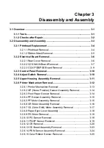
Страница 61: ...2 3 12 Other Sensor Circuits 2 31 ...
Страница 160: ...Chapter 6 Maintenance 6 1 Maintenance 6 1 6 1 1 Lubrication and Adhesion 6 1 ...
Страница 171: ...DLQ 3000 Rev A A 6 ...
Страница 172: ...Appendix Rev A A 7 A 2 Circuit Diagrams Figure A 2 C210 MAIN Board Circuit Diagram 1 2 ...
Страница 173: ...DLQ 3000 Rev A A 8 ...
Страница 174: ...Appendix Rev A A 9 Figure A 3 C210 MAIN Board Circuit Diagram 2 2 ...
Страница 175: ...DLQ 3000 Rev A A 10 ...
Страница 177: ...DLQ 3000 Rev A A 12 Figure A 5 C124 PSB Board Circuit Diagram ...
Страница 179: ...DLQ 3000 Rev A A 14 A 3 Circuit Board Component Layout Figure A 7 C210 MAIN Board Component Layout 1 2 ...
Страница 180: ...Appendix Rev A A 15 Figure A 8 C210 MAIN Board Component Layout 2 2 ...
Страница 181: ...DLQ 3000 Rev A A 16 Figure A 9 C124 PSB Board Component Layout ...
Страница 182: ...Appendix Rev A A 17 Figure A 10 C124 PSE Board Component Layout ...
Страница 189: ...EPSON SEIKO EPSON CORPORATION ...