


DLQ-3000+
Rev. A
5-14
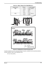
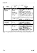
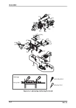
5.4 Repair of C210 MAIN Board Component
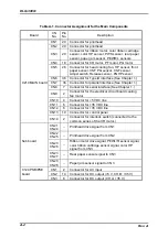
Table 5-11. Repair of C210 MAIN Board
Condition
Cause
Check point
Solution
Symptom : The printer does not operate at all.
Reset signal is
not released.
Reset circuit is
defective.
After turning on the printer, check if
the signal output from pin 1 on
IC22
and
IC20
is
LOW
for a while.
(See Note 1.)
Replace the
main control
board.
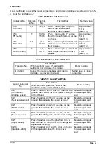
The signal
VOUT
is not output.
Check if +5 V is normal. Then check
pins 3 and 4 of the connector
CN10
.
Replace the
PSB/PSE
board.
CPU
is not
functioning.
The clock signal
is not output.
Check that the waveform shown
below is output from pins 74 and 75
of
IC16
.
Figure 5-11. CPU Clock Signal Waveform
Replace the
main control
board or
CR1
.
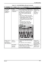
Flash-ROM is
defective.
Reload the printer control program.
(See Chapter 3.)
If the condition is not corrected,
Flash-ROM is defective.
Replace the
main control
board.
CPU is defective.
Check pins
27 – 43
of
IC16
for change
in the signals
HIGH
and
LOW
.
Figure 5-12. CPU Data Bus
Replace the
main control
board.
Note:
1. Reset signal is originally output from
IC22
to reset Flash-ROM. Then, it is sent to the
CPU
and
gate array via
IC20
.
Содержание DLQ-3000 Minerva+
Страница 1: ...EPSON 24 PIN DOT MATRIX PRINTER EPSON DLQ 3000 SERVICE MANUAL SEIKO EPSON CORPORATION 4008259 ...
Страница 5: ...v REVISION SHEET Revision Issued Data Contents Rev A August 21 1997 First Release ...
Страница 61: ...2 3 12 Other Sensor Circuits 2 31 ...
Страница 160: ...Chapter 6 Maintenance 6 1 Maintenance 6 1 6 1 1 Lubrication and Adhesion 6 1 ...
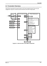
Страница 171: ...DLQ 3000 Rev A A 6 ...
Страница 172: ...Appendix Rev A A 7 A 2 Circuit Diagrams Figure A 2 C210 MAIN Board Circuit Diagram 1 2 ...
Страница 173: ...DLQ 3000 Rev A A 8 ...
Страница 174: ...Appendix Rev A A 9 Figure A 3 C210 MAIN Board Circuit Diagram 2 2 ...
Страница 175: ...DLQ 3000 Rev A A 10 ...
Страница 177: ...DLQ 3000 Rev A A 12 Figure A 5 C124 PSB Board Circuit Diagram ...
Страница 179: ...DLQ 3000 Rev A A 14 A 3 Circuit Board Component Layout Figure A 7 C210 MAIN Board Component Layout 1 2 ...
Страница 180: ...Appendix Rev A A 15 Figure A 8 C210 MAIN Board Component Layout 2 2 ...
Страница 181: ...DLQ 3000 Rev A A 16 Figure A 9 C124 PSB Board Component Layout ...
Страница 182: ...Appendix Rev A A 17 Figure A 10 C124 PSE Board Component Layout ...
Страница 189: ...EPSON SEIKO EPSON CORPORATION ...