


DLQ-3000+
Rev. A
3-4
3.2.1 Printhead Replacement
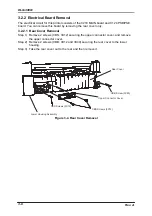
3.2.1.1 Printhead Removal
You can remove the printhead without removing the upper housing assembly or printer
mechanism.
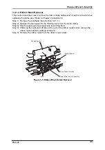
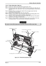
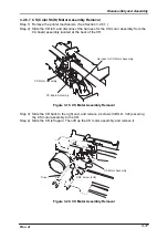
Step 1) Open the printer cover assembly, and remove 2 screws (CBS, 3X12) securing the
printhead.
Step 2) Lift up the printhead a little and release the head FFCs from the clips in the CR
assembly. Then disconnect the FFCs from the printhead.
Step 3) Remove the printhead from the CR assembly.
Head FFC
Printhead
CBS Screws (3X12)
Figure 3-2. Printhead Removal
Perform “Platen gap adjustment” after replacing the printhead.
When replacing the printhead, replace the ribbon mask along with the printhead.
CAUTION
Содержание DLQ-3000 Minerva+
Страница 1: ...EPSON 24 PIN DOT MATRIX PRINTER EPSON DLQ 3000 SERVICE MANUAL SEIKO EPSON CORPORATION 4008259 ...
Страница 5: ...v REVISION SHEET Revision Issued Data Contents Rev A August 21 1997 First Release ...
Страница 61: ...2 3 12 Other Sensor Circuits 2 31 ...
Страница 160: ...Chapter 6 Maintenance 6 1 Maintenance 6 1 6 1 1 Lubrication and Adhesion 6 1 ...
Страница 171: ...DLQ 3000 Rev A A 6 ...
Страница 172: ...Appendix Rev A A 7 A 2 Circuit Diagrams Figure A 2 C210 MAIN Board Circuit Diagram 1 2 ...
Страница 173: ...DLQ 3000 Rev A A 8 ...
Страница 174: ...Appendix Rev A A 9 Figure A 3 C210 MAIN Board Circuit Diagram 2 2 ...
Страница 175: ...DLQ 3000 Rev A A 10 ...
Страница 177: ...DLQ 3000 Rev A A 12 Figure A 5 C124 PSB Board Circuit Diagram ...
Страница 179: ...DLQ 3000 Rev A A 14 A 3 Circuit Board Component Layout Figure A 7 C210 MAIN Board Component Layout 1 2 ...
Страница 180: ...Appendix Rev A A 15 Figure A 8 C210 MAIN Board Component Layout 2 2 ...
Страница 181: ...DLQ 3000 Rev A A 16 Figure A 9 C124 PSB Board Component Layout ...
Страница 182: ...Appendix Rev A A 17 Figure A 10 C124 PSE Board Component Layout ...
Страница 189: ...EPSON SEIKO EPSON CORPORATION ...