


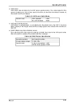

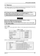
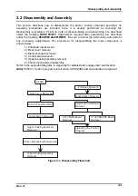

Operating Principles
Rev. A
2-27
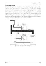
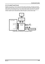
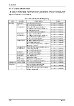
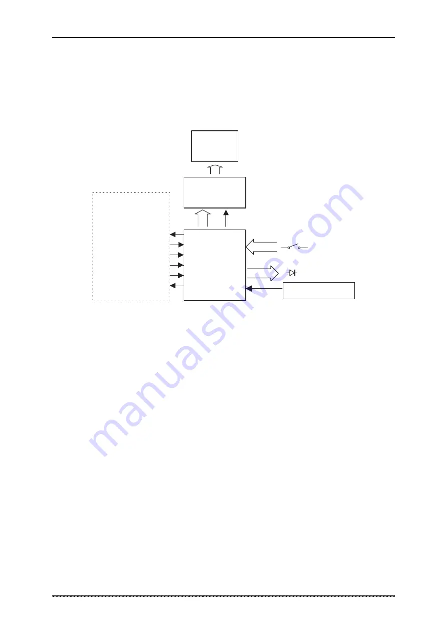
2.3.8 Control Panel Circuit
E05A89, the gate array for the control panel I/F, has the LCD driver, LED driver and panel
switch input circuit built in. The serial I/F is used for signal transmission between the control
panel and the main control board. The cover open sensor signal on the logic line is directly
sent to the main control board via the control panel board. If the printer cover is open, an
interlock switch function is activated for safety and puts the printer inactive state.
L C D
P N L T O M A I N
M A I N T O P N L
S C K
+ 5 V
G N D
L E D s
R S T
D A T A
C A S E O P E N
L C D D r i v e r
G a t e A r r a y
E 0 5 A 8 9
S w i t c h
C o v e r O p e n S e n s o r
C o n t r o l B o a r d
Figure 2-20. Control Panel Circuit Block Diagram
Содержание DLQ-3000 Minerva+
Страница 1: ...EPSON 24 PIN DOT MATRIX PRINTER EPSON DLQ 3000 SERVICE MANUAL SEIKO EPSON CORPORATION 4008259 ...
Страница 5: ...v REVISION SHEET Revision Issued Data Contents Rev A August 21 1997 First Release ...
Страница 61: ...2 3 12 Other Sensor Circuits 2 31 ...
Страница 160: ...Chapter 6 Maintenance 6 1 Maintenance 6 1 6 1 1 Lubrication and Adhesion 6 1 ...
Страница 171: ...DLQ 3000 Rev A A 6 ...
Страница 172: ...Appendix Rev A A 7 A 2 Circuit Diagrams Figure A 2 C210 MAIN Board Circuit Diagram 1 2 ...
Страница 173: ...DLQ 3000 Rev A A 8 ...
Страница 174: ...Appendix Rev A A 9 Figure A 3 C210 MAIN Board Circuit Diagram 2 2 ...
Страница 175: ...DLQ 3000 Rev A A 10 ...
Страница 177: ...DLQ 3000 Rev A A 12 Figure A 5 C124 PSB Board Circuit Diagram ...
Страница 179: ...DLQ 3000 Rev A A 14 A 3 Circuit Board Component Layout Figure A 7 C210 MAIN Board Component Layout 1 2 ...
Страница 180: ...Appendix Rev A A 15 Figure A 8 C210 MAIN Board Component Layout 2 2 ...
Страница 181: ...DLQ 3000 Rev A A 16 Figure A 9 C124 PSB Board Component Layout ...
Страница 182: ...Appendix Rev A A 17 Figure A 10 C124 PSE Board Component Layout ...
Страница 189: ...EPSON SEIKO EPSON CORPORATION ...