


Disassembly and Assembly
Rev. A
3-19
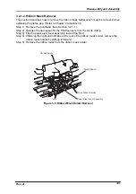
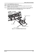
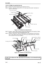
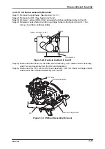
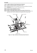
3.2.6.9 PG Motor Removal
Step 1) Remove the printer mechanism. (See Section 3.2.6.1.)
Step 2) Remove the harness for the PG motor from the cable clamp in the printer
mechanism.
Step 3) Remove 2 screws (CP, O, 3X6) securing the PG motor to the printer mechanism,
and remove the PG motor.
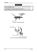
WORK POINT
Backlash for the PG motor and the combination gear(8, 26) is 0.1
±±
0.05 mm.
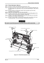
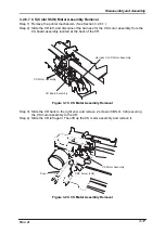
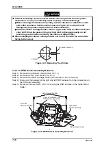
3.2.6.10 PG Sensor Removal
Step 1) Remove the printer mechanism. (See Section 3.2.6.1.)
Step 2) Remove the PG motor. (See Section 3.2.6.9.)
Step 3) Remove the harness for the PG sensor from the cable clamp.
Step 4) Remove 1 screw (CBS, 3x6) securing the PG sensor to the printer mechanism, and
remove the PG sensor.
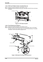
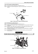
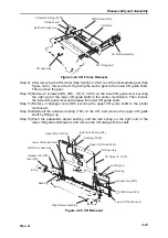
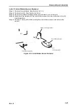
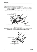
3.2.6.11 PGHP Sensor Removal
Step 1) Remove the printer mechanism. (See Section 3.2.6.1.)
Step 2) Remove the PG motor. (See Section 3.2.6.9.)
Step 3) Remove 1 intermediate gear from the left side of the printer mechanism.
Step 4) Remove 1 screw (CP, 2X8) securing the PGHP sensor to the left of the printer
mechanism, and remove the PGHP sensor.
C B S S c r e w ( 3 X 6 )
P G S e n s o r
P G M o t o r
C P S c r e w ( O , 3 X 6 )
C P S c r e w ( 2 X 8 )
P G H P S e n s o r
L e f t F r a m e A s s e m b l y
I n t e r m e d i a t e G e a r
C o m b i n a t i o n G e a r ( 8 , 2 6 )
Figure 3-22. PG Adjustment Mechanism Removal
Содержание DLQ-3000 Minerva+
Страница 1: ...EPSON 24 PIN DOT MATRIX PRINTER EPSON DLQ 3000 SERVICE MANUAL SEIKO EPSON CORPORATION 4008259 ...
Страница 5: ...v REVISION SHEET Revision Issued Data Contents Rev A August 21 1997 First Release ...
Страница 61: ...2 3 12 Other Sensor Circuits 2 31 ...
Страница 160: ...Chapter 6 Maintenance 6 1 Maintenance 6 1 6 1 1 Lubrication and Adhesion 6 1 ...
Страница 171: ...DLQ 3000 Rev A A 6 ...
Страница 172: ...Appendix Rev A A 7 A 2 Circuit Diagrams Figure A 2 C210 MAIN Board Circuit Diagram 1 2 ...
Страница 173: ...DLQ 3000 Rev A A 8 ...
Страница 174: ...Appendix Rev A A 9 Figure A 3 C210 MAIN Board Circuit Diagram 2 2 ...
Страница 175: ...DLQ 3000 Rev A A 10 ...
Страница 177: ...DLQ 3000 Rev A A 12 Figure A 5 C124 PSB Board Circuit Diagram ...
Страница 179: ...DLQ 3000 Rev A A 14 A 3 Circuit Board Component Layout Figure A 7 C210 MAIN Board Component Layout 1 2 ...
Страница 180: ...Appendix Rev A A 15 Figure A 8 C210 MAIN Board Component Layout 2 2 ...
Страница 181: ...DLQ 3000 Rev A A 16 Figure A 9 C124 PSB Board Component Layout ...
Страница 182: ...Appendix Rev A A 17 Figure A 10 C124 PSE Board Component Layout ...
Страница 189: ...EPSON SEIKO EPSON CORPORATION ...