


Operating Principles
Rev. A
2-31
2.3.12 Other Sensor Circuits
This printer is equipped with other sensors to monitor printer condition in detailed.
Head thermistor
The head thermistor detects temperatures around the head and sends the information
with the analog signal to the CPU A/C converter using the internal resistance (16.5K
Ω
).
This information prevents worn-out and shorter life of the drive coils due to over duty
printing, and protects printhead during operation at low temperatures.
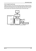
+35 VDC monitor
The CPU monitors head drive voltage by detecting the +35 VDC line with the internal A/D
converter. The printer changes the print mode according to the detected change in the
head drive voltage.
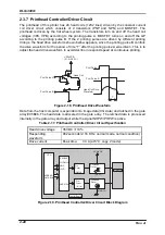
Cover open sensor
Cover open sensor, located at the top right of the upper housing, detects the printer
cover’s open/close condition. The output signal is reversed by the digital transistor and
input to the CPU interruption port via the filter circuit which consists of the resistor and
condenser.
Table 2-21. Cover Open Sensor Specification
Detecting method
Mechanical switch
Power supply voltage
5 VDC
±
5%
Detecting mode
Cover open : LOW
Cover closed : HIGH
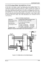
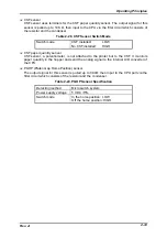
Color HP (Home Position) sensor
Color HP sensor uses a photo interrupter system. When the home position for the color
ribbon cartridge is detected, the output signal is pulled up to 10 K
Ω
, then input to the
CPU port via the filter circuit which consists of the resistance and the condenser.
Table 2-22. Color HP Sensor Specification
Detecting method
Photo interrupter system
Output system
Open collector system
Resistance to voltage:30V or less
Sink current : 0.3 mA or less
Switch mode
In the home position : LOW
Off the home position : HIGH
Note) After the printer is powered on or the cover open is detected, the printer refers to
the switching mode of this sensor.
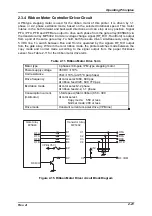
Rear paper sensor
Rear paper sensor is located on the right side of the paper jam sensor. The output signal
is pulled up by 6.2 K
Ω
, then input to the CPU port via the filter circuit which consists of
the resistor and the condenser.
Table 2-23. Rear Paper Sensor Specification
Detecting method
Mechanical switch (connector switch) system
Rated
current/voltage
0.6
−
1.0mA, 5VDC
±
5%
Switch mode
Paper detected : LOW
No paper detected : HIGH
Содержание DLQ-3000 Minerva+
Страница 1: ...EPSON 24 PIN DOT MATRIX PRINTER EPSON DLQ 3000 SERVICE MANUAL SEIKO EPSON CORPORATION 4008259 ...
Страница 5: ...v REVISION SHEET Revision Issued Data Contents Rev A August 21 1997 First Release ...
Страница 61: ...2 3 12 Other Sensor Circuits 2 31 ...
Страница 160: ...Chapter 6 Maintenance 6 1 Maintenance 6 1 6 1 1 Lubrication and Adhesion 6 1 ...
Страница 171: ...DLQ 3000 Rev A A 6 ...
Страница 172: ...Appendix Rev A A 7 A 2 Circuit Diagrams Figure A 2 C210 MAIN Board Circuit Diagram 1 2 ...
Страница 173: ...DLQ 3000 Rev A A 8 ...
Страница 174: ...Appendix Rev A A 9 Figure A 3 C210 MAIN Board Circuit Diagram 2 2 ...
Страница 175: ...DLQ 3000 Rev A A 10 ...
Страница 177: ...DLQ 3000 Rev A A 12 Figure A 5 C124 PSB Board Circuit Diagram ...
Страница 179: ...DLQ 3000 Rev A A 14 A 3 Circuit Board Component Layout Figure A 7 C210 MAIN Board Component Layout 1 2 ...
Страница 180: ...Appendix Rev A A 15 Figure A 8 C210 MAIN Board Component Layout 2 2 ...
Страница 181: ...DLQ 3000 Rev A A 16 Figure A 9 C124 PSB Board Component Layout ...
Страница 182: ...Appendix Rev A A 17 Figure A 10 C124 PSE Board Component Layout ...
Страница 189: ...EPSON SEIKO EPSON CORPORATION ...