


Disassembly and Assembly
Rev. A
3-21
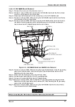
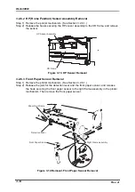
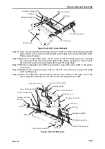
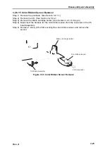
E x t e n s i o n S p r i n g ( 3 2 7 5 )
C R B e l t L e v e r
B e l t S u b P u l l e y S e t
C R A s s e m b l y
C R T i m i n g B e l t
C R M o t o r A s s e m b l y
C R F r a m e
C B S S c r e w ( 3 X 6 )
Figure 3-25. CR Frame Removal
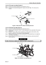
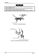
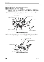
Step 9) After removing the PG motor (See Section 3.2.6.9,) and the intermediate gear (See
Figure 3-22.), remove the E-ring fixing the sector gear to the lower CR guide shaft.
Then remove the gear.
Step 10) Remove 2 screws (CBS, 3X6 ; CP, O, 3X10) on the lower CR guide lever securing
the right end of the lower CR guide shaft to the printer mechanism. Then remove
the lower CR guide lever and release the lower CR guide shaft.
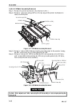
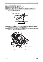
Step 11) Remove 2 hexagon nuts (OW) securing the upper CR guide shaft to the printer
mechanism.
Step 12) Dismount the extension spring (154) on the CR, and remove the upper CR guide
shaft by lifting it up.
Step 13) Push the parallelism adjust bushing and the leaf spring on the right end of the
lower CR guide shaft inward, and remove the CR along with the shaft.
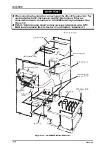
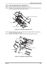
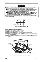
U p p e r P l a i n O i l P a d
L o w e r C R G u i d e S h a f t
L e f t F r a m e A s s e m b l y
H e x a g o n N u t ( O W )
G e a r ( 4 0 )
E - r i n g
E x t e n s i o n S p r i n g ( 1 5 4 )
B u s h i n g ( 1 4 . 0 4 )
U p p e r C R G u i d e S h a f t
C R A s s e m b l y
C P S c r e w ( 0 , 3 X 1 0 )
L e a f S p r i n g
B u s h i n g
C B S S c r e w ( 3 X 6 )
L o w e r C R G u i d e L e v e r
R i g h t F r a m e A s s e m b l y
B u s h i n g
H e x a g o n N u t ( O W )
Figure 3-26. CR Removal
Содержание DLQ-3000 Minerva+
Страница 1: ...EPSON 24 PIN DOT MATRIX PRINTER EPSON DLQ 3000 SERVICE MANUAL SEIKO EPSON CORPORATION 4008259 ...
Страница 5: ...v REVISION SHEET Revision Issued Data Contents Rev A August 21 1997 First Release ...
Страница 61: ...2 3 12 Other Sensor Circuits 2 31 ...
Страница 160: ...Chapter 6 Maintenance 6 1 Maintenance 6 1 6 1 1 Lubrication and Adhesion 6 1 ...
Страница 171: ...DLQ 3000 Rev A A 6 ...
Страница 172: ...Appendix Rev A A 7 A 2 Circuit Diagrams Figure A 2 C210 MAIN Board Circuit Diagram 1 2 ...
Страница 173: ...DLQ 3000 Rev A A 8 ...
Страница 174: ...Appendix Rev A A 9 Figure A 3 C210 MAIN Board Circuit Diagram 2 2 ...
Страница 175: ...DLQ 3000 Rev A A 10 ...
Страница 177: ...DLQ 3000 Rev A A 12 Figure A 5 C124 PSB Board Circuit Diagram ...
Страница 179: ...DLQ 3000 Rev A A 14 A 3 Circuit Board Component Layout Figure A 7 C210 MAIN Board Component Layout 1 2 ...
Страница 180: ...Appendix Rev A A 15 Figure A 8 C210 MAIN Board Component Layout 2 2 ...
Страница 181: ...DLQ 3000 Rev A A 16 Figure A 9 C124 PSB Board Component Layout ...
Страница 182: ...Appendix Rev A A 17 Figure A 10 C124 PSE Board Component Layout ...
Страница 189: ...EPSON SEIKO EPSON CORPORATION ...