


Operating Principles
Rev. A
2-5
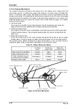
Manual PG adjustment function
This function allows the user to set the proper PG manually by setting the PG adjust
lever to one of the steps from -1 to 9. The selected step is converted into 4-bit data using
adjustment switches and the data is transferred to the controller circuit, where the PG is
determined based on the information.
Table 2-3. PG and PG Adjust Switch
PG lever
Adjust switch condition
Corresponding paper
PG width
Print mode
Steps
#1
#2
#3
#4
Thickness (PT)
(mm)
-1
{
{
−
{
0.06=<PT<=0.11
0.35
Normal
0
−
{
−
{
0.06=<PT<=0.11
0.39
Normal
1
{
−
−
{
0.11<PT<=0.15
0.43
Normal
2
−
−
−
{
0.15<PT<=0.19
0.46
Normal
3
{
{
{
−
0.19<PT<=0.25
0.50
Copy 1/2
4
−
{
{
−
0.25<PT<=0.30
0.55
Copy 1/2
5
{
−
{
−
0.30<PT<=0.36
0.61
Copy 1/2
6
−
−
{
−
0.36<PT<=0.42
0.67
Copy 1/2
7
{
{
−
−
0.42<PT<=0.46
0.71
Copy 1/2
8
−
{
−
−
0.46<PT<=0.49
0.74
Copy 1/2
9
{
−
−
−
0.49<PT<=0.53
0.78
Copy 1/2
Automatic
−
−
−
−
0.06=<PT<=0.53
Note 1
Note 2
Note)
1. PG width corresponds to the detected paper thickness.
2. Copy mode is used for paper with the thickness of 0.2 mm or more.
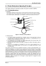
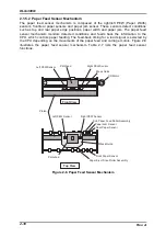
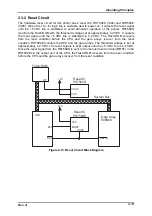
Automatic PG adjustment function
PG is automatically adjusted based on the paper thickness detected paper thickness
sensor which consists of the slit disc and the photo-electric transfer. Paper thickness is
detected in the following order:
1. PG home position is detected.
2. The gap between the platen surface and the printhead is measured by pressing
the printhead to the platen through the ribbon mask and ink ribbon.
3. The paper thickness is by pressing the printhead to the paper surface through the
ribbon mask and ink ribbon.
4. The printer sets the proper PG based on the measurement done in the step 2 and
3.
PG is determined for each paper loading action. When the CSF is used, this function is
activated when the printer is turned on. It is also performed when the paper quantity
sensor in the hopper is reset. However, no printing is performed during this operation.
(Refer to Section 2.3.10.)
Содержание DLQ-3000 Minerva+
Страница 1: ...EPSON 24 PIN DOT MATRIX PRINTER EPSON DLQ 3000 SERVICE MANUAL SEIKO EPSON CORPORATION 4008259 ...
Страница 5: ...v REVISION SHEET Revision Issued Data Contents Rev A August 21 1997 First Release ...
Страница 61: ...2 3 12 Other Sensor Circuits 2 31 ...
Страница 160: ...Chapter 6 Maintenance 6 1 Maintenance 6 1 6 1 1 Lubrication and Adhesion 6 1 ...
Страница 171: ...DLQ 3000 Rev A A 6 ...
Страница 172: ...Appendix Rev A A 7 A 2 Circuit Diagrams Figure A 2 C210 MAIN Board Circuit Diagram 1 2 ...
Страница 173: ...DLQ 3000 Rev A A 8 ...
Страница 174: ...Appendix Rev A A 9 Figure A 3 C210 MAIN Board Circuit Diagram 2 2 ...
Страница 175: ...DLQ 3000 Rev A A 10 ...
Страница 177: ...DLQ 3000 Rev A A 12 Figure A 5 C124 PSB Board Circuit Diagram ...
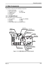
Страница 179: ...DLQ 3000 Rev A A 14 A 3 Circuit Board Component Layout Figure A 7 C210 MAIN Board Component Layout 1 2 ...
Страница 180: ...Appendix Rev A A 15 Figure A 8 C210 MAIN Board Component Layout 2 2 ...
Страница 181: ...DLQ 3000 Rev A A 16 Figure A 9 C124 PSB Board Component Layout ...
Страница 182: ...Appendix Rev A A 17 Figure A 10 C124 PSE Board Component Layout ...
Страница 189: ...EPSON SEIKO EPSON CORPORATION ...