


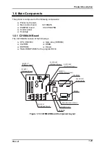


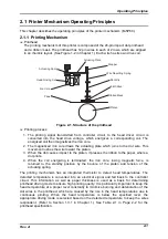


Operating Principles
Rev. A
2-7
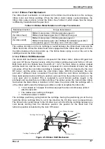
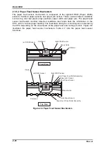
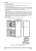
2.1.4.1 Ribbon Feed Mechanism
The ribbon feed mechanism is composed of the ribbon feed mechanism in the carriage,
ribbon motor and ribbon cartridge. When the ribbon motor rotates counterclockwise, the
ribbon drive pulley is driven to feed the ribbon. See Table 2-5 which shows how the torque
is differently transmitted via the gear train.
Table 2-5. Ribbon Motor Rotation and Torque Transmission
Rotational direction
Torque transmission
C.C.W.
(for ribbon feed)
Ribbon motor pinion
→
Ribbon planetary gear
→
Ribbon transmission gear train
→
Ribbon drive gear
C.W.
(for ribbon shift)
Ribbon motor pinion
→
Ribbon planetary gear
→
Ribbon transmission gear (A)
→
Ribbon transmission gear (B)
→
CS reduction gear
→
CS drive cam
→
CS drive lever
The endless ink ribbon in the ink cartridge is routed between the ribbon feed roller and the
ribbon hold roller. When the ribbon feed roller engaged with the ribbon drive gear is driven,
the ribbon between the rollers winds up. The ribbon brake spring is set at the exit in the
cartridge to wind the ribbon tightly.
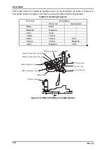
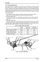
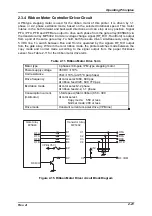
2.1.4.2 Ribbon Shift Mechanism
The ribbon shift mechanism, which is composed of the ribbon motor, ribbon shift gear train
and color HP (Home Position) sensor, shifts the ribbon cartridge back and forth on CR unit.
Both black and color ribbons have the width of 1 inch. The black ribbon is entirely soaked
with the black ink, and the color ribbon is composed of 4 colored bands of black, red, blue
and yellow. When the color ribbon cartridge is installed on the CR, it is detected by the color
HP sensor, and the printer enters the color ribbon mode. With this mechanism, the color
print with 7 different colors is enabled. The printer shifts the color ribbon cartridge to the
black band position before shifting to another color each time the printer is turned on or the
cover open error is cleared. This is operated to avoid ribbon’s getting caught in the
printhead and resultant failure in ribbon shifting. The printer enters the monochrome ribbon
mode when the black ribbon is installed. In this mode, the printer shifts the cartridge with ¼
of the ribbon width under the following condition in order to lengthen the ribbon life:
•
10 cut sheets or 10 pages of continuous paper has been continuously printed
after the last shift.
•
The release lever setting is changed.
•
Continuous paper is loaded.
The cartridge positioning spring behind the cartridge, having the positioning pin at the top,
holds the ribbon cartridge firmly to act in the direction the CS drive lever is pressed down.
The ribbon motor sends torque to the CS drive lever, which shifts the cartridge between any
color bands, starting from the reference position, the position for the black belt. The
reference position is detected by the color HP sensor.
C R
C o l o r R i b b o n C a r t r i d g e
B l a c k
C y a n
M a g e n t a
Y e l l o w
C S D r i v e L e v e r
C a r t r i d g e P o s i t i o n i n g S p r i n g
C a r t r i d g e P o s i t i o n i n g P i n
Figure 2-5. Ribbon Shift Mechanism
Содержание DLQ-3000 Minerva+
Страница 1: ...EPSON 24 PIN DOT MATRIX PRINTER EPSON DLQ 3000 SERVICE MANUAL SEIKO EPSON CORPORATION 4008259 ...
Страница 5: ...v REVISION SHEET Revision Issued Data Contents Rev A August 21 1997 First Release ...
Страница 61: ...2 3 12 Other Sensor Circuits 2 31 ...
Страница 160: ...Chapter 6 Maintenance 6 1 Maintenance 6 1 6 1 1 Lubrication and Adhesion 6 1 ...
Страница 171: ...DLQ 3000 Rev A A 6 ...
Страница 172: ...Appendix Rev A A 7 A 2 Circuit Diagrams Figure A 2 C210 MAIN Board Circuit Diagram 1 2 ...
Страница 173: ...DLQ 3000 Rev A A 8 ...
Страница 174: ...Appendix Rev A A 9 Figure A 3 C210 MAIN Board Circuit Diagram 2 2 ...
Страница 175: ...DLQ 3000 Rev A A 10 ...
Страница 177: ...DLQ 3000 Rev A A 12 Figure A 5 C124 PSB Board Circuit Diagram ...
Страница 179: ...DLQ 3000 Rev A A 14 A 3 Circuit Board Component Layout Figure A 7 C210 MAIN Board Component Layout 1 2 ...
Страница 180: ...Appendix Rev A A 15 Figure A 8 C210 MAIN Board Component Layout 2 2 ...
Страница 181: ...DLQ 3000 Rev A A 16 Figure A 9 C124 PSB Board Component Layout ...
Страница 182: ...Appendix Rev A A 17 Figure A 10 C124 PSE Board Component Layout ...
Страница 189: ...EPSON SEIKO EPSON CORPORATION ...