


Chapter 2
Operating Principle
2.1 Printer Mechanism Operating Principles............................................. 2-1
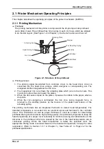
2.1.1 Printing Mechanism ...................................................................... 2-1
2.1.2 CR (Carriage) Mechanism ............................................................ 2-3
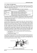
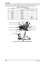
2.1.3 PG (Platen Gap) Adjustment Mechanism.................................... 2-4
2.1.4 Ribbon Feed/Ribbon Shift Mechanism........................................ 2-6
2.1.4.1 Ribbon Feed Mechanism..................................................... 2-7
2.1.4.2 Ribbon Shift Mechanism...................................................... 2-7
2.1.5 Paper Feed Mechanism ................................................................ 2-9
2.1.5.1 Core of the Paper Feed Mechanism.................................... 2-9
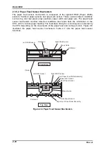
2.1.5.2 Paper Feed Sensor Mechanism ........................................ 2-10
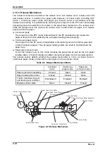
2.1.5.3 Release Mechanism .......................................................... 2-12
2.2 Circuit Operating Principles................................................................ 2-13
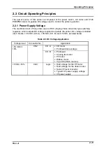
2.2.1 Power Supply Voltage................................................................. 2-13
2.2.2 Power Supply Circuit Operation ................................................ 2-14
2.3 Controller Circuit.................................................................................. 2-15
2.3.1 Interface Circuit ........................................................................... 2-18
2.3.2 Reset Circuit ................................................................................ 2-19
2.3.3 Memory Back-up Circuit ............................................................. 2-20
2.3.4 Ribbon Motor Controller/Driver Circuit ..................................... 2-21
2.3.5 PF (Paper Feed) Motor Controller/Driver Circuit...................... 2-22
2.3.6 CR (Carriage) Motor Controller/Driver Circuit .......................... 2-23
2.3.6.1 Bi-D Adjustment Function.................................................. 2-25
2.3.6.2 Interlock Function .............................................................. 2-25
2.3.7 Printhead Controller/Driver Circuit............................................ 2-26
2.3.8 Control Panel Circuit................................................................... 2-27
2.3.9 PG (Platen Gap) Motor Driver Circuit ........................................ 2-28
2.3.10 Paper Thickness Detecting Circuit .......................................... 2-29
2.3.11 Paper Jam Sensor ..................................................................... 2-30
Содержание DLQ-3000 Minerva+
Страница 1: ...EPSON 24 PIN DOT MATRIX PRINTER EPSON DLQ 3000 SERVICE MANUAL SEIKO EPSON CORPORATION 4008259 ...
Страница 5: ...v REVISION SHEET Revision Issued Data Contents Rev A August 21 1997 First Release ...
Страница 61: ...2 3 12 Other Sensor Circuits 2 31 ...
Страница 160: ...Chapter 6 Maintenance 6 1 Maintenance 6 1 6 1 1 Lubrication and Adhesion 6 1 ...
Страница 171: ...DLQ 3000 Rev A A 6 ...
Страница 172: ...Appendix Rev A A 7 A 2 Circuit Diagrams Figure A 2 C210 MAIN Board Circuit Diagram 1 2 ...
Страница 173: ...DLQ 3000 Rev A A 8 ...
Страница 174: ...Appendix Rev A A 9 Figure A 3 C210 MAIN Board Circuit Diagram 2 2 ...
Страница 175: ...DLQ 3000 Rev A A 10 ...
Страница 177: ...DLQ 3000 Rev A A 12 Figure A 5 C124 PSB Board Circuit Diagram ...
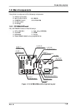
Страница 179: ...DLQ 3000 Rev A A 14 A 3 Circuit Board Component Layout Figure A 7 C210 MAIN Board Component Layout 1 2 ...
Страница 180: ...Appendix Rev A A 15 Figure A 8 C210 MAIN Board Component Layout 2 2 ...
Страница 181: ...DLQ 3000 Rev A A 16 Figure A 9 C124 PSB Board Component Layout ...
Страница 182: ...Appendix Rev A A 17 Figure A 10 C124 PSE Board Component Layout ...
Страница 189: ...EPSON SEIKO EPSON CORPORATION ...