


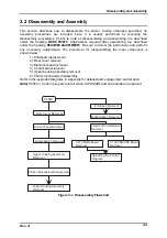


Disassembly and Assembly
Rev. A
3-9
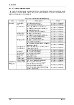
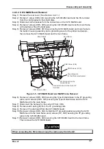
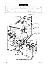
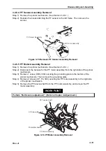
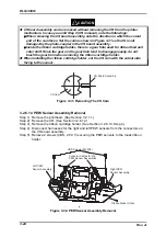
3.2.2.3 C124 PSB/PSE Board Removal
Step 1) Remove the rear cover. (See Section 3.2.2.1.)
Step 2) Remove 2 screws (CBS, 3X6) securing the power supply board and the C124
PSB/PSE board to the shield plate.
Step 3) Disconnect all harnesses one by one from the connectors on the C124 PSB/PSE
board as taking out the C124 PSB/PSE board on the power supply frame
gradually, then remove the C124 PSB/PSE board.
C 1 2 4 P S B / P S E B o a r d
C B S S c r e w s ( 3 X 6 )
P o w e r s u u p l y F r a m e
S h i e l d P l a t e
Figure 3-7. C124 PSB/PSE Board Removal
Содержание DLQ-3000 Minerva+
Страница 1: ...EPSON 24 PIN DOT MATRIX PRINTER EPSON DLQ 3000 SERVICE MANUAL SEIKO EPSON CORPORATION 4008259 ...
Страница 5: ...v REVISION SHEET Revision Issued Data Contents Rev A August 21 1997 First Release ...
Страница 61: ...2 3 12 Other Sensor Circuits 2 31 ...
Страница 160: ...Chapter 6 Maintenance 6 1 Maintenance 6 1 6 1 1 Lubrication and Adhesion 6 1 ...
Страница 171: ...DLQ 3000 Rev A A 6 ...
Страница 172: ...Appendix Rev A A 7 A 2 Circuit Diagrams Figure A 2 C210 MAIN Board Circuit Diagram 1 2 ...
Страница 173: ...DLQ 3000 Rev A A 8 ...
Страница 174: ...Appendix Rev A A 9 Figure A 3 C210 MAIN Board Circuit Diagram 2 2 ...
Страница 175: ...DLQ 3000 Rev A A 10 ...
Страница 177: ...DLQ 3000 Rev A A 12 Figure A 5 C124 PSB Board Circuit Diagram ...
Страница 179: ...DLQ 3000 Rev A A 14 A 3 Circuit Board Component Layout Figure A 7 C210 MAIN Board Component Layout 1 2 ...
Страница 180: ...Appendix Rev A A 15 Figure A 8 C210 MAIN Board Component Layout 2 2 ...
Страница 181: ...DLQ 3000 Rev A A 16 Figure A 9 C124 PSB Board Component Layout ...
Страница 182: ...Appendix Rev A A 17 Figure A 10 C124 PSE Board Component Layout ...
Страница 189: ...EPSON SEIKO EPSON CORPORATION ...