


DLQ-3000+
Rev. A
2-4
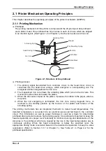
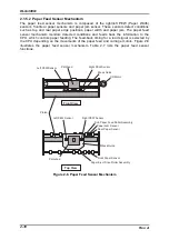
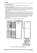
2.1.3 PG (Platen Gap) Adjustment Mechanism
PG adjustment is made manually and automatically. In the manual PG adjustment mode,
the proper PG is originally set for the paper to be loaded by manually operating the PG
adjust lever located at the left front of the printer. On the other hand, the automatic PG
adjustment function lets the printer automatically measure the paper thickness and set the
proper PG for the thickness. This mode is activated by setting the PG adjust lever to the
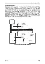
automatic side. Figure 2-3 shows the PG adjustment mechanism.
Slit Disc
Paper Thickness Sensor
CR Guide Shaft
Printhead (CR Unit)
Ink Ribbon
Ribbon Mask
Paper
PG Motor
Pinion Gear
Combination Gear
Sector Gear
PGHP Sensor
Platen
Figure 2-3. PG adjustment Mechanism
The PG adjustment mechanism located at the left top of the printer mechanism unit consists
of the PG motor, CR guide shaft, sectorial gear, combination gear, PG home position
sensor, and paper thickness sensor., After the PG is determined by the controller circuit
according to the paper thickness, the PG motor rotates corresponding amount. The torque
from the PG motor is transmitted via the motor pinion gear, combination gear and sectorial
gear to the CR guide shaft. Since the shaft is eccentric, the CR on the shaft moves from or
toward the platen as the shaft moves, depending on the direction the motor rotates. Seeing
from the left side of the printer mechanism, the clockwise or counterclockwise rotation of the
CR guide shaft narrows or widens the PG, respectively. The PG home position is detected
when the sectorial gear pushes the actuator on the PG home position sensor.
Содержание DLQ-3000 Minerva+
Страница 1: ...EPSON 24 PIN DOT MATRIX PRINTER EPSON DLQ 3000 SERVICE MANUAL SEIKO EPSON CORPORATION 4008259 ...
Страница 5: ...v REVISION SHEET Revision Issued Data Contents Rev A August 21 1997 First Release ...
Страница 61: ...2 3 12 Other Sensor Circuits 2 31 ...
Страница 160: ...Chapter 6 Maintenance 6 1 Maintenance 6 1 6 1 1 Lubrication and Adhesion 6 1 ...
Страница 171: ...DLQ 3000 Rev A A 6 ...
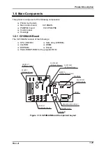
Страница 172: ...Appendix Rev A A 7 A 2 Circuit Diagrams Figure A 2 C210 MAIN Board Circuit Diagram 1 2 ...
Страница 173: ...DLQ 3000 Rev A A 8 ...
Страница 174: ...Appendix Rev A A 9 Figure A 3 C210 MAIN Board Circuit Diagram 2 2 ...
Страница 175: ...DLQ 3000 Rev A A 10 ...
Страница 177: ...DLQ 3000 Rev A A 12 Figure A 5 C124 PSB Board Circuit Diagram ...
Страница 179: ...DLQ 3000 Rev A A 14 A 3 Circuit Board Component Layout Figure A 7 C210 MAIN Board Component Layout 1 2 ...
Страница 180: ...Appendix Rev A A 15 Figure A 8 C210 MAIN Board Component Layout 2 2 ...
Страница 181: ...DLQ 3000 Rev A A 16 Figure A 9 C124 PSB Board Component Layout ...
Страница 182: ...Appendix Rev A A 17 Figure A 10 C124 PSE Board Component Layout ...
Страница 189: ...EPSON SEIKO EPSON CORPORATION ...