


Operating Principles
Rev. A
2-29
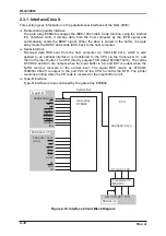
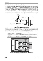
2.3.10 Paper Thickness Detecting Circuit
PG is detected by the paper thickness sensor which consists of the slit disc and the photo-
electric transfer element. See Table 2-19 and Figure 2-22 for the paper thickness sensor
specification and paper thickness sensor circuit block diagram, respectively.
Table 2-19. Paper Thickness Sensor Specification
Detecting method
Photo interrupt system
Power supply voltage
5 VDC
±
5%
Outputs
In 2 channels, TTL level
Minimum detecting thickness
0.008 mm
Detecting range
0 to 0.53 mm
+5V
PENCA
PENCB
T
PENCA
PENCB
E05B46
Gate Array
Paper Thickness Sensor
PHA
Condition
Figure 2-22. Paper Thickness Sensor Circuit Block Diagram
To determine the paper thickness, the printer monitors the waveforms output from the PG
sensor, as shown in Figure 2-22. “T” output for PHD shows a period of time in which 2-
chanel pulses PENCA and PENCB change for 180°. The printer counts the different
numbers of pulses output while the printhead moves from PG home position to the platen
surface and surface of the loaded paper to determine the paper thickness which
corresponds to the difference between 2 values. The numbers of pulses are counted in the
following order:
1. After the printer power is turned on, the PG home position is detected.
2. Distance between the printhead and platen surface is measured
While the printhead is moving from the PG home position toward the platen surface,
the waveform stays at a constant level and when that status exceeds for specified
period of time, the printer assumes that the printhead has reached the platen. The
PG motor consequently stops rotating and the numbers of the pulses output during
this operation is counted and the value is fed back to the CPU.
3. The printhead returns to the stand-by position.
4. The distance between the PG home position and loaded paper surface is measured in
the same procedure.
Paper thickness is determined for each paper loaded. The last values for the platen position
and PG before power-off are stored in the EEPROM and are no lost if the printer power is
turned off.
Содержание DLQ-3000 Minerva+
Страница 1: ...EPSON 24 PIN DOT MATRIX PRINTER EPSON DLQ 3000 SERVICE MANUAL SEIKO EPSON CORPORATION 4008259 ...
Страница 5: ...v REVISION SHEET Revision Issued Data Contents Rev A August 21 1997 First Release ...
Страница 61: ...2 3 12 Other Sensor Circuits 2 31 ...
Страница 160: ...Chapter 6 Maintenance 6 1 Maintenance 6 1 6 1 1 Lubrication and Adhesion 6 1 ...
Страница 171: ...DLQ 3000 Rev A A 6 ...
Страница 172: ...Appendix Rev A A 7 A 2 Circuit Diagrams Figure A 2 C210 MAIN Board Circuit Diagram 1 2 ...
Страница 173: ...DLQ 3000 Rev A A 8 ...
Страница 174: ...Appendix Rev A A 9 Figure A 3 C210 MAIN Board Circuit Diagram 2 2 ...
Страница 175: ...DLQ 3000 Rev A A 10 ...
Страница 177: ...DLQ 3000 Rev A A 12 Figure A 5 C124 PSB Board Circuit Diagram ...
Страница 179: ...DLQ 3000 Rev A A 14 A 3 Circuit Board Component Layout Figure A 7 C210 MAIN Board Component Layout 1 2 ...
Страница 180: ...Appendix Rev A A 15 Figure A 8 C210 MAIN Board Component Layout 2 2 ...
Страница 181: ...DLQ 3000 Rev A A 16 Figure A 9 C124 PSB Board Component Layout ...
Страница 182: ...Appendix Rev A A 17 Figure A 10 C124 PSE Board Component Layout ...
Страница 189: ...EPSON SEIKO EPSON CORPORATION ...