


DLQ-3000+
Rev. A
4-4
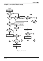
4.2.1.2 PG Reference Value
Platen gap reference value measurement
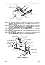
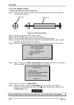
Step 1) Turn the platen roller to set the white eccentricity mark to the top. (This operation
sets the PG narrowest.)
P l a t e n R o l l e r
W h i t e M a r k
A - A '
A '
A
Figure 4-2. Eccentricity Mark
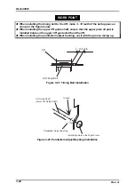
Step 2) Set the release lever to the cut sheet mode.
Step 3) Set the PG adjust lever to the “Auto” (the lowest).
Step 4) Put the interlock switch and cover open sensor disabled condition.
Step 5) Connect the printer and the host computer with a parallel interface cable, and turn
the printer on first and then the computer.
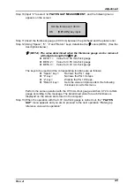
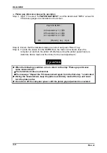
Step 6) Start the adjustment program, and the main menu below appears on the screen:
DLQ-3000+/VP-4200
CHECK PROGRAM
REV.
∗
1. Platen Gap Adjustment
2. Bi-D Adjustment
3. END
If ready, press 1-3 and the “RETURN” key.
Step 7) Input “1” to select “1. Platen Gap Adjustment” and press the “Return” key, and the
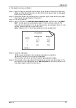
platen gap adjustment menu below appears on the screen:
PLATEN GAP
1. ALPHA INPUT
2. PLATEN GAP MEASUREMENT
3. PLATEN GAP INPUT
4. PLATEN GAP VERIFICATION
ALPHA = 0
Step 8) Input “1” to select “1. ALPHA INPUT”.
Step 9) When the monitor show the ”ALPHA INPUT” menu, input the value which is
marked on the printhead nose side for the “
α
” value, and the menu returns to the
“PLATEN GAP“ menu.
Unless ALPHA value is input, the program does not proceed to the next operation.
CAUTION
Содержание DLQ-3000 Minerva+
Страница 1: ...EPSON 24 PIN DOT MATRIX PRINTER EPSON DLQ 3000 SERVICE MANUAL SEIKO EPSON CORPORATION 4008259 ...
Страница 5: ...v REVISION SHEET Revision Issued Data Contents Rev A August 21 1997 First Release ...
Страница 61: ...2 3 12 Other Sensor Circuits 2 31 ...
Страница 160: ...Chapter 6 Maintenance 6 1 Maintenance 6 1 6 1 1 Lubrication and Adhesion 6 1 ...
Страница 171: ...DLQ 3000 Rev A A 6 ...
Страница 172: ...Appendix Rev A A 7 A 2 Circuit Diagrams Figure A 2 C210 MAIN Board Circuit Diagram 1 2 ...
Страница 173: ...DLQ 3000 Rev A A 8 ...
Страница 174: ...Appendix Rev A A 9 Figure A 3 C210 MAIN Board Circuit Diagram 2 2 ...
Страница 175: ...DLQ 3000 Rev A A 10 ...
Страница 177: ...DLQ 3000 Rev A A 12 Figure A 5 C124 PSB Board Circuit Diagram ...
Страница 179: ...DLQ 3000 Rev A A 14 A 3 Circuit Board Component Layout Figure A 7 C210 MAIN Board Component Layout 1 2 ...
Страница 180: ...Appendix Rev A A 15 Figure A 8 C210 MAIN Board Component Layout 2 2 ...
Страница 181: ...DLQ 3000 Rev A A 16 Figure A 9 C124 PSB Board Component Layout ...
Страница 182: ...Appendix Rev A A 17 Figure A 10 C124 PSE Board Component Layout ...
Страница 189: ...EPSON SEIKO EPSON CORPORATION ...