v
Liebert SRC
™
User Manual
List of Figures
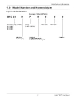
Figure 1-1: Product Nomenclature . . . . . . . . . . . . . . . . . . . . . . . . . . . . . . . . . . . . . . . . . . . . . . . . . . . . . . . . . . . . . . 9
Figure 2-1: Indoor Unit Parts and Functions . . . . . . . . . . . . . . . . . . . . . . . . . . . . . . . . . . . . . . . . . . . . . . . . . . . . . 11
Figure 2-2: Outdoor Unit Parts and Functions . . . . . . . . . . . . . . . . . . . . . . . . . . . . . . . . . . . . . . . . . . . . . . . . . . . . 11
Figure 2-3: Thermostat parts and functions . . . . . . . . . . . . . . . . . . . . . . . . . . . . . . . . . . . . . . . . . . . . . . . . . . . . . . 12
Figure 2-4: Accessories . . . . . . . . . . . . . . . . . . . . . . . . . . . . . . . . . . . . . . . . . . . . . . . . . . . . . . . . . . . . . . . . . . . . . 12
Figure 2-5: Icon descriptions and functions . . . . . . . . . . . . . . . . . . . . . . . . . . . . . . . . . . . . . . . . . . . . . . . . . . . . . . 13
Figure 3-1: Oceanside placement using a windbreak . . . . . . . . . . . . . . . . . . . . . . . . . . . . . . . . . . . . . . . . . . . . . . 21
Figure 3-2: Oceanside placement using a building . . . . . . . . . . . . . . . . . . . . . . . . . . . . . . . . . . . . . . . . . . . . . . . . 22
Figure 3-3: Outdoor unit mounting methods . . . . . . . . . . . . . . . . . . . . . . . . . . . . . . . . . . . . . . . . . . . . . . . . . . . . . 23
Figure 3-4: Outdoor-unit clearances . . . . . . . . . . . . . . . . . . . . . . . . . . . . . . . . . . . . . . . . . . . . . . . . . . . . . . . . . . . 24
Figure 3-5: Outdoor-unit sunroof/awning clearances. . . . . . . . . . . . . . . . . . . . . . . . . . . . . . . . . . . . . . . . . . . . . . . 25
Figure 3-6: Clearances when there are obstacles on both air-inlet and air-outlet sides . . . . . . . . . . . . . . . . . . . . 25
Figure 3-7: Clearances when there are obstacles above and on both air-inlet and air-outlet sides . . . . . . . . . . . 25
Figure 3-8: Indoor unit clearance requirements . . . . . . . . . . . . . . . . . . . . . . . . . . . . . . . . . . . . . . . . . . . . . . . . . . . 26
Figure 3-9: Installation-plate screws for SRC18. . . . . . . . . . . . . . . . . . . . . . . . . . . . . . . . . . . . . . . . . . . . . . . . . . . 27
Figure 3-10: Piping clearance for SRC18 plate . . . . . . . . . . . . . . . . . . . . . . . . . . . . . . . . . . . . . . . . . . . . . . . . . . . 27
Figure 3-11: Installation-plate screws for SRC24 and SRC36 . . . . . . . . . . . . . . . . . . . . . . . . . . . . . . . . . . . . . . . . 28
Figure 3-12: Piping clearance for SRC24 and SRC36 plate . . . . . . . . . . . . . . . . . . . . . . . . . . . . . . . . . . . . . . . . . 28
Figure 3-13: Drilling a piping hole . . . . . . . . . . . . . . . . . . . . . . . . . . . . . . . . . . . . . . . . . . . . . . . . . . . . . . . . . . . . . 29
Figure 3-14: Hook the top of the unit to the plate. . . . . . . . . . . . . . . . . . . . . . . . . . . . . . . . . . . . . . . . . . . . . . . . . . 29
Figure 3-15: Move the bottom of the unit to the plate and attach to plate . . . . . . . . . . . . . . . . . . . . . . . . . . . . . . . 30
Figure 3-16: Insert and tighten screws. . . . . . . . . . . . . . . . . . . . . . . . . . . . . . . . . . . . . . . . . . . . . . . . . . . . . . . . . . 30
Figure 3-17: Rear view of indoor unit. . . . . . . . . . . . . . . . . . . . . . . . . . . . . . . . . . . . . . . . . . . . . . . . . . . . . . . . . . . 31
Figure 5-1: Creating a flared fitting . . . . . . . . . . . . . . . . . . . . . . . . . . . . . . . . . . . . . . . . . . . . . . . . . . . . . . . . . . . . 36
Figure 5-2: Flared-connection dimensions. . . . . . . . . . . . . . . . . . . . . . . . . . . . . . . . . . . . . . . . . . . . . . . . . . . . . . . 37
Figure 5-3: Tightening the flare nuts . . . . . . . . . . . . . . . . . . . . . . . . . . . . . . . . . . . . . . . . . . . . . . . . . . . . . . . . . . . 37
Figure 5-4: Keep piping capped while storing . . . . . . . . . . . . . . . . . . . . . . . . . . . . . . . . . . . . . . . . . . . . . . . . . . . . 38
Figure 5-5: Refrigerant-pipe brazing . . . . . . . . . . . . . . . . . . . . . . . . . . . . . . . . . . . . . . . . . . . . . . . . . . . . . . . . . . . 39
Figure 5-6: Installing piping above and below an obstacle . . . . . . . . . . . . . . . . . . . . . . . . . . . . . . . . . . . . . . . . . . 42
Figure 5-7: Coiled expansion loops and offsets . . . . . . . . . . . . . . . . . . . . . . . . . . . . . . . . . . . . . . . . . . . . . . . . . . . 44
Figure 5-8: Pipe-hanger details . . . . . . . . . . . . . . . . . . . . . . . . . . . . . . . . . . . . . . . . . . . . . . . . . . . . . . . . . . . . . . . 45
Figure 5-9: Typical pipe-support location for a change in pipe direction . . . . . . . . . . . . . . . . . . . . . . . . . . . . . . . . 46
Figure 5-10: Pipe sleeve options . . . . . . . . . . . . . . . . . . . . . . . . . . . . . . . . . . . . . . . . . . . . . . . . . . . . . . . . . . . . . . 47
Figure 5-11: Typical arrangement of pipe and cables in a utility conduit . . . . . . . . . . . . . . . . . . . . . . . . . . . . . . . . 48
Figure 5-12: System layout . . . . . . . . . . . . . . . . . . . . . . . . . . . . . . . . . . . . . . . . . . . . . . . . . . . . . . . . . . . . . . . . . . 49
Figure 5-13: Piping installation and connection overview . . . . . . . . . . . . . . . . . . . . . . . . . . . . . . . . . . . . . . . . . . . 50
Figure 5-14: Pipe-support spacing for outdoors. . . . . . . . . . . . . . . . . . . . . . . . . . . . . . . . . . . . . . . . . . . . . . . . . . . 50
Figure 5-15: Proper pipe and cable bundling—cut-away. . . . . . . . . . . . . . . . . . . . . . . . . . . . . . . . . . . . . . . . . . . . 51
Figure 5-16: Bundling and taping piping and cables . . . . . . . . . . . . . . . . . . . . . . . . . . . . . . . . . . . . . . . . . . . . . . . 51
Figure 5-17: Piping/Trap when indoor unit is above outdoor unit. . . . . . . . . . . . . . . . . . . . . . . . . . . . . . . . . . . . . . 52
Figure 5-18: Piping/Trap when indoor unit is below outdoor unit . . . . . . . . . . . . . . . . . . . . . . . . . . . . . . . . . . . . . . 52
Содержание Liebert SRC Series
Страница 1: ...Liebert SRC User Manual Mini Split Cooling System ...
Страница 2: ......
Страница 18: ...Safety Symbols Liebert SRC User Manual 8 Page intentionally left blank ...
Страница 20: ...Model Number and Nomenclature Liebert SRC User Manual 10 Page intentionally left blank ...
Страница 28: ...Product Introduction Liebert SRC User Manual 18 Page intentionally left blank ...
Страница 122: ...Troubleshooting Liebert SRC User Manual 112 Page intentionally left blank ...
Страница 123: ......


