background image

Troubleshooting

Liebert

®

 SRC

 User Manual

110

10.6 Refrigerant Leaks

ASHRAE Standards 15-2010 and 34-2010 offer guidelines that address refrigerant safety and the 
maximum allowable concentration of refrigerant in an occupied space. Refrigerant will dissipate into the 
atmosphere, but a certain volume of air is required for this to occur safely. For R410A refrigerant, the 
maximum allowable concentration is 0.026 lbs/ft

3

 per 1,000 ft

3

 of air in an occupied space. Buildings with 

24-hour occupancy allow half of that concentration.

1

ASHRAE Standards 15 and 34 assume that if a system develops a leak, its entire refrigerant charge will 
dump into the area where the leak occurs. To meet ASHRAE Standards 15 and 34, calculate the 
refrigerant concentration that may occur in the smallest room volume on the system, and compare the 
results to the maximum allowable concentration number.

1

 Also consult state and local codes with regard to 

refrigerant safety.

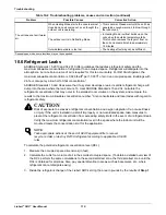
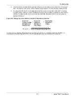
To calculate the potential refrigerant concentration level (RCL):

1. Measure the occupied space dimensions (in feet).

2. Calculate the cubic foot volume of air in the smallest occupied space. (To obtain a detailed overview of 

the RCL, perform the same calculations to the second smallest zone, the third smallest zone until the 
RCL is obtained for all zones. Also, pay special attention to areas such as basements, etc., where 
refrigerant cannot dissipate easily.)

3. Divide the refrigerant change of the Liebert SRC serving the area in pounds by the results of 

Step 1

.

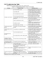
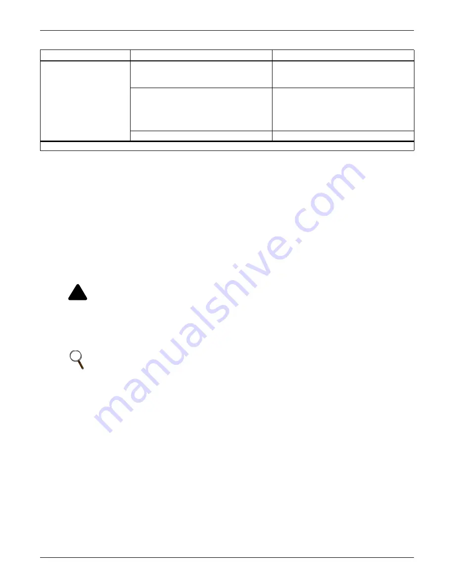
The unit does not emit warm 
air.

When Heating Mode starts, the vane is almost 
closed and no air comes out, even thought the 
outdoor unit is operating.

• This is normal. Please wait until the unit has 

generated enough warm air to blow through 
the indoor unit.

The outdoor unit is in Defrosting Mode.

• In Heating Mode, ice/frost builds up on the 

coils when the outside temperature falls. 
This function removes the layer of frost on 
the coil and should finish in approximately 
15 minutes.

Outside temperature is too low.

• The heating effect may not be sufficient.

!

CAUTION

Risk of exposure to excessive refrigerant concentration and oxygen depletion. Can cause illness 
or injury. If the unit is installed in a small improperly or non-ventilated space, take measures to 
prevent the refrigerant concentration from exceeding safety limits in the event of a refrigerant leak.
Verify the maximum refrigerant concentration level in the space where the indoor unit will be 
mounted meets the concentration limit for the application.

NOTE

Take appropriate actions at the end of HVAC equipment life to recover, 
recycle, reclaim or destroy R410A refrigerant according to applicable US EPA 
rules.

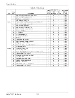
Table 10-2 Troubleshooting problems, causes and correction (continued)

Problem

Possible Causes

Corrective Action

Depending on mode, some functions may not be supported.

Содержание Liebert SRC Series

Страница 1: ...Liebert SRC User Manual Mini Split Cooling System ...

Страница 2: ......

Страница 3: ...straints 23 3 2 3 Snow and Ice Conditions 24 3 3 Clearance requirements 24 3 3 1 Outdoor Unit Clearance 24 3 3 2 Indoor Unit Clearance 26 3 4 Installing the Indoor Unit 26 3 4 1 Mounting the Installation Plate to the Wall SRC18 26 3 4 2 Mounting the Installation Plate to the Wall SRC24 SRC36 28 3 4 3 Drilling a Piping Hole in the Wall 29 3 4 4 Mounting the Indoor Unit to the Plate 29 3 4 5 Prepare...

Страница 4: ...tdoor Unit 52 5 3 2 3 Bundling and Trap when Indoor Unit is below Outdoor Unit 52 5 3 3 Routing the Drain Hose for Indoor Unit 53 5 3 4 Installing a Drain Hose on the Outdoor Unit 54 5 3 5 Connecting Piping on the SCR18 Outdoor Unit 55 5 3 6 Connecting Piping on the SCR24 and SCR36 Outdoor Unit 57 5 3 7 Connecting Piping on the Indoor Unit 59 5 4 Piping Insulation 63 5 4 1 Minimum Requirements for...

Страница 5: ...ht 89 7 7 Setting Fahrenheit Celsius 89 7 8 Setting Optional Functions 90 7 9 Setting Temperature Range 90 8 0 Operation 91 8 1 Operating the Unit 91 8 2 Automatic Unit Restart 92 8 3 Enabling Cooling only Mode 92 8 4 Disabling Cooling only Mode 93 8 5 Standard Operation 93 8 5 1 Selecting Cooling Mode 93 8 5 2 Selecting Power Cooling 93 8 5 3 Selecting Heating Mode 94 8 5 4 Selecting Dehumidifica...

Страница 6: ...Schedule 99 8 7 3 Weekly Schedule 99 8 7 4 Copy Paste a Schedule 100 8 7 5 Schedule a Holiday 100 8 7 6 Delete all Schedules 100 9 0 Maintenance 101 9 1 Cleaning the Air Filter 102 9 1 1 Cleaning the Air Filter on Type 1 Units 102 9 1 2 Cleaning the Air Filter on Type 2 Units 102 9 2 Cleaning the Optional 3M or Triple Filter 104 10 0 Troubleshooting 105 10 1 Self diagnosis at the Indoor Unit 105 1...

Страница 7: ...plate 28 Figure 3 13 Drilling a piping hole 29 Figure 3 14 Hook the top of the unit to the plate 29 Figure 3 15 Move the bottom of the unit to the plate and attach to plate 30 Figure 3 16 Insert and tighten screws 30 Figure 3 17 Rear view of indoor unit 31 Figure 5 1 Creating a flared fitting 36 Figure 5 2 Flared connection dimensions 37 Figure 5 3 Tightening the flare nuts 37 Figure 5 4 Keep pipi...

Страница 8: ...5 37 Typical butt joint insulation at indoor unit 64 Figure 5 38 Typical refrigerant flare fitting insulation 64 Figure 5 39 Removing service valve caps from outdoor unit for purging 66 Figure 5 40 Evacuation set up 67 Figure 5 41 Leak test set up diagram 68 Figure 6 1 Indoor and Outdoor wiring and communications cable diagram 72 Figure 6 2 Typical ring terminal 72 Figure 6 3 Proper and Improper p...

Страница 9: ...r filter from Type 2 unit 103 Figure 9 6 Inserting cleaned air filter on the hooks of the Type 2 unit 103 Figure 9 7 Push down on the hooks of the Type 2 unit 103 Figure 9 8 Removing 3M Triple filters from indoor unit 104 Figure 9 9 Replacing 3M Triple filters in the indoor unit 104 Figure 10 1 Error codes displayed at the thermostat 106 Figure 10 2 Error code display for SRC18 107 Figure 10 3 Err...

Страница 10: ...quivalent piping length for piping components 45 Table 5 10 Utility conduit sizes 48 Table 5 11 Heat pump unit refrigerant pipe connections All brazed type 48 Table 5 12 Refrigerant piping system limitations 49 Table 5 13 Outdoor unit drain connection components 54 Table 5 14 Tightening torque for flare nuts 56 Table 5 15 Tightening torque for flare nuts 58 Table 5 16 Insulation guidelines for typ...

Страница 11: ...ce valves on the unit until all non condensibles have been removed from the piping system and authorization to do so has been obtained from the commissioning agent WARNING Risk of excessive refrigerant pressure Can cause equipment damage serious injury or death Do not run the compressor with the service valves closed WARNING Arc flash and electric shock hazard Can cause serious injury or death Ope...

Страница 12: ... Part1 CSA C 22 1 as applicable and appropriate The information contained in the manual is intended for use only by Liebert trained and a qualified service technicians who are familiar with the appropriate safety procedures and equipped with the proper tools and test instruments Power cord replacement must only be be performed by authorized personnel using only Liebert specified replacement parts ...

Страница 13: ...thing away from moving parts Do not open the inlet grille of the unit during operation Do not insert hands or other objects through the inlet or outlet when the unit is plugged in Do not touch the electrostatic filter if the unit includes one WARNING Risk of electric shock Can cause injury or death Periodically check power cord and plug for damage Damaged power cords must be replaced by the manufa...

Страница 14: ...radio communication equipment may cause the unit to operate improperly The unit may also affect such equipment by creating electrical noise that disturbs medical treatment or image broadcasting CAUTION Risk of contact with extremely hot and cold surfaces Can cause injury Refrigerant piping is extremely hot or cold during unit operation Do not touch the refrigerant piping during or after operation ...

Страница 15: ...step on or fall onto it Do not install the unit on a defective stand Periodically check that the outdoor frame is not damaged NOTICE Risk of leaking water Can cause building and equipment damage Install the drain hose as specified in this manual to ensure adequate drainage and periodically check for damage obstruction and leaks NOTICE Risk of leaking refrigerant Can cause equipment malfunction and...

Страница 16: ...ed to provide cooling and heating for electronic and telecommunications equipment Oil steam sulfuric smoke etc can significantly reduce the performance of the unit or damage its parts NOTE If the leaking battery fluid has been swallowed wash off the inside of the mouth thoroughly and consult a doctor Do not drink the water drained from the unit Do not use the product for special purposes such as p...

Страница 17: ...ng and maintenance servicing instructions in the literature accompanying the appliance Dangerous Voltage Warns about the presence of uninsulated dangerous voltage within the product s enclosure that may be of sufficient magnitude to constitute a risk of electric shock to persons Power On Indicates the principal On Off switch is in the On position Power Off Indicates the principal On Off switch is ...

Страница 18: ...Safety Symbols Liebert SRC User Manual 8 Page intentionally left blank ...

Страница 19: ...enclature Figure 1 1 Product Nomenclature H 0 0 N AHRI Type H Heat pump Placeholder Nominal Capacity in Btu h 12 12 000 18 18 000 24 24 000 36 36 000 Revision Example SRC24 HPN000 P Voltage P 208 230 1 60 24 Unit Type N Indoor evaporator C Outdoor condensing unit 0 Placeholder SRC ...

Страница 20: ...Model Number and Nomenclature Liebert SRC User Manual 10 Page intentionally left blank ...

Страница 21: ...d up the fan to cool or warm indoor air quickly within a short period of time Open windows regularly for ventilation The indoor air quality may deteriorate if the unit is used for long durations Clean the air filter once every 2 weeks Dust and impurities collected in the air filter may block the air flow or weaken the cooling dehumidifying functions Figure 2 1 Indoor Unit Parts and Functions Figur...

Страница 22: ... button 4 Set back button 13 Up down left and right buttons 5 Operation mode select button 14 On Off button 6 Wireless thermostat receiver not included on some models 15 Heating temperature setpoint 7 Sub function button 16 Set Cancel button 8 Ventilation button 17 Exit button 9 Reservation button NOTE Some functions may not be available or displayed depending on unit type No Description No Descri...

Страница 23: ...ting mode automatically Operating in cooling mode Operating in dehumidification mode Operating in heating mode Operating in fan only mode 2 Sub functions Plasma purification filter is operating Energy saving cooling mode operating in limited temperature range Automatic drying is operating Electric heater is operating in heater mode Humidifier is operating Automatic fan function on indoor unit The ...

Страница 24: ...mporarily operate in a mode Override schedule occupied unoccupied Operate in set back mode 7 State Monitoring Command received from central controller or outdoor unit Slave indoor unit to a heat pump system Prevents changing to a mode that is incompatible with the current mode of the outdoor unit Outdoor unit is operating Indoor unit is pre heating Defrost is operating Function is not applied 8 Sc...

Страница 25: ... SUN Sunday MON Monday TUE Tuesday WED Wednesday THU Thursday FRI Friday SAT Saturday Number of the weekly schedule event Schedule time AM PM Schedule time hour minute min minute hr hour Weekly schedule occupied un occupied state Copy Paste schedule data Section Icon Description ...

Страница 26: ...e value between cooling and heating setpoints Set current time Set timer for schedule override Set up default setback for cooling heating temperature setpoints Clear the air filter cleaning alarm Check the indoor unit air filter and clean if necessary Table 2 1 Unit electrical data Model Nom Tons Compressor Qty Compressor A Cool Heat Fan Qty ODU Fan A IDU Fan A MCA A MOP A SRC18 1 1 2 1 14 6 14 6 ...

Страница 27: ... refrigerant leaks Can cause equipment damage illness serious injury and death from suffocation Do not use piping that is not approved for use in high pressure refrigerant systems Refrigerant leaks in non ventilated spaces could cause oxygen depletion levels that are dangerous to humans Follow accepted safety practices for refrigerant storage discharging and charging NOTE Piping wall thickness mus...

Страница 28: ...Product Introduction Liebert SRC User Manual 18 Page intentionally left blank ...

Страница 29: ... the system may malfunction 3 Remove any snow that has accumulated 3 15 16 inches or more on the top of the outdoor unit 4 Place the outdoor unit on a raised platform at least 19 11 16 inches higher than the average annual snowfall for the area In environments where there is a possibility of heavy snow the frame height must be more than 2 times the amount of average annual snowfall and should not ...

Страница 30: ...talling multiple outdoor units avoid placing the units where discharge of one outdoor unit will blow into the inlet side of an adjacent unit 3 1 2 Oceanside Applications Using a Windbreak to Shield the Unit from Sea Wind Avoid installing the unit where it would be directly exposed to ocean winds Install the outdoor unit on the side of the building opposite from direct ocean winds Select a location...

Страница 31: ...Installation 21 Liebert SRC User Manual Figure 3 1 Oceanside placement using a windbreak No Description 1 Windbreak 2 Sea wind 1 2 ...

Страница 32: ... building or larger structure must be used to shield the outdoor unit from direct exposure to the sea wind The unit should be placed on the side of the building directly opposite to the direction of the wind as shown in Figure 3 2 Figure 3 2 Oceanside placement using a building No Description 1 Building 2 Sea wind 2 2 1 1 ...

Страница 33: ...to support the weight of the unit Avoid placing the unit in a low lying area where water may accumulate When installing the outdoor unit on the wall or roof top anchor the mounting base securely to account for wind earthquake or vibration 3 2 2 Tie downs and Wind Restraints The strength of the inverter system frame is adequate to be used with field provided wind restraint tie downs The overall tie...

Страница 34: ...ce requirements as illustrated in Figure 3 4 3 3 1 Outdoor Unit Clearance Specific clearance requirements are for the wall mount systems Figure 3 4 shows the overall minimum clearances that must be observed for safe operation and adequate airflow around the outdoor unit Figure 3 4 Outdoor unit clearances When placing the outdoor unit under an overhang awning sunroof or other roof like structure ob...

Страница 35: ...ir inlet and air outlet sides Figure 3 7 Clearances when there are obstacles above and on both air inlet and air outlet sides NOTE In Figures 3 6 and 3 7 the obstacle on the outlet side is lower than the outdoor unit More than 12 More than 12 More than 28 Unit Inch More than 24 Minimum 28 Minimum 12 Unit Inch Minimum 12 79 24 Minimum 28 Unit Inch ...

Страница 36: ...nd best practices when mounting the indoor unit s plate to a wall WARNING Risk of electrical shock Can cause injury or death When choosing a location for the wall mount plate be sure to take into consideration routing of wiring for power outlets within the wall Avoid contact with hazardous voltage wiring Use caution when drilling holes through the walls for the purposes of piping connections Refer...

Страница 37: ...mount the plate as follows Use the provided screws and mount the installation plate horizontally by aligning the centerline using a leveling tool Observe the left and right rear piping clearance when drilling into the wall Figure 3 10 Piping clearance for SRC18 plate A Type B Type Unit Inch Ø2 19 32 Ø2 19 32 2 11 16 2 3 16 Right rear piping Left rear piping Installation Plate Measuring Tape Measur...

Страница 38: ...earance for SRC24 and SRC36 plate WARNING Risk of electrical shock Can cause injury or death When choosing a location for the wall mount plate be sure to take into consideration routing of wiring for power outlets within the wall Avoid contact with hazardous voltage wiring Use caution when drilling holes through the walls for the purposes of piping connections Refer to 3 4 3 Drilling a Piping Hole...

Страница 39: ...e as shown in Figure 3 13 with a bushing and sleeve covering The sleeve and bushing prevents damage to the tubing bundling of the piping Figure 3 13 Drilling a piping hole 3 4 4 Mounting the Indoor Unit to the Plate 1 Hook the indoor unit onto the upper portion of the installation plate Figure 3 14 2 Engage the hooks at the top of the indoor unit with the upper edge of the installation plates Make...

Страница 40: ... insert the screws pay attention to the position of the piping through any wall as shown in the figure Figure 3 16 Insert and tighten screws 3 4 5 Prepare for Piping Electrical Connection 1 To prepare the indoor unit for piping disengage the bottom on the indoor unit from the installation plate by reversing Step 3 of 3 4 4 Mounting the Indoor Unit to the Plate This separates the bottom of the indo...

Страница 41: ...e for the steps 1 Connect a low pressure gauge with manifold hose to the charge port on the gas line service valve 2 Open the gas line service valve half way CAUTION Risk of inhalation of refrigerant gas Can cause illness and injury Never air purge with refrigerant as it can cause refrigerant leakage NOTE Use a vacuum pump that can evacuate down to 500 microns 1 If moisture remains in the piping a...

Страница 42: ... Turn on the cooling unit s power switch and start cooling mode operation 8 3 Enabling Cooling only Mode 6 Observe the pressure gauge reading When the gauge reads 1 to 0 5 kg cm2 14 2 to 7 1 psig fully close the gas line valve and immediately turn of the cooling unit Pump down is complete and all refrigerant should be collected into the outdoor unit ...

Страница 43: ...nstant 3 psi while brazing Installation Refer to the details in the Installation section for more information on any procedure Refrigerant Piping ___ 1 All pipe materials were properly stored capped and clean All burrs were removed after cutting and pipe ends were reamed before brazing ___ 2 During refrigerant pipe installation for each segment of pipe a record was made of the pipe length includin...

Страница 44: ...it was installed per all local electrical code requirements ___ 6 Factory supplied cable was used between the indoor unit and the thermostat No cables were spliced and no wire caps are present ___ 7 Communication type RS 485 BUS type ___ 8 All communication cables were a minimum of 18 AWG 4 conductor shielded and stranded with insulation material per local code Cable segment shield were tied toget...

Страница 45: ... excessive bending in one specific area on its length 2 Braze the pips to the service valve pipe stem of the outdoor unit WARNING Risk of refrigerant leaks Can cause equipment malfunction injury sickness and death from suffocation due to oxygen depletion in closed non ventilated areas When selecting flare fittings always use a 45 fitting rated for use with high pressure refrigerant R410A Verify th...

Страница 46: ...d introducing foreign materials into the pipe B Slide the flare nut onto the copper tube 3 Flaring the pipe end Use the proper size flaring tool to finish flared connections as shown in Figure 5 1 Always create a 45 flare when working with R410A Refer to the Warning preceding this procedure Figure 19 Creating a Flare Fitting Copper tube 90 Slanted Uneven Rough Pipe Reamer Point down Flare nut Copp...

Страница 47: ... backup wrench as shown in Figure 5 3 Figure 5 3 Tightening the flare nuts Table 5 1 Flared connection dimensions Pipe A Thickness Vapor in O D Liquid in O D Vapor in Liquid in Vapor in Liquid in 1 2 1 4 1 8 1 16 1 8 1 8 5 8 3 8 1 8 1 16 1 16 1 8 NOTE Do not use polyolyester POE or any other type of mineral oil as a thread lubricant These lubricants are not compatible with PVE oil used in this sys...

Страница 48: ...llary tubes become clogged Refrigerant gas leaks shortages Refrigerant oil degradation Poor insulation of the compressor System does not operate properly Solutions Remove moisture from the piping Piping ends should remain capped until connections are complete Do not install piping on a rainy day Connect piping properly at the unit s side Remove caps only after the piping is cut the burrs are remov...

Страница 49: ...ions Use a tubing cutter do not use a saw to cut pipe De burr and clean all cuts before assembly Store pipe stock in a dry place Keep pipe capped and clean Use adapters to assemble different sizes of pipe Do not use flux soft solder or anti oxidant agents Use a 15 silver phosphorous copper brazing alloy to avoid overheating and produce good flow Protect isolation valves electronic expansion valves...

Страница 50: ...sing through pipe hangers inside conduit and or sleeves must not be compressed Protects insulation inside handers and supports with a second layer All pipe insulation exposed to the sun and outdoor elements shall be properly protected with PVC aluminum vapor barrier or alternatively placed in a weather resistant enclosure such as a pipe rack with a top cover and meet local codes The design enginee...

Страница 51: ...minal Wall Thickness in Weight lb ft Cubic ft per Linear ft 1 4 0 250 0 030 0 081 00020 3 8 0 375 0 030 0 126 00054 0 032 0 134 00053 1 2 0 500 0 035 0 198 00101 0 032 0 182 00103 5 8 0 625 0 040 0 285 00162 0 035 0 251 00168 3 4 0 750 0 042 0 362 00242 0 042 0 362 00242 7 8 0 875 0 045 0 455 00336 0 045 0 455 00336 1 1 8 1 125 0 050 0 655 00573 0 050 0 655 00573 1 All dimensions provided are in a...

Страница 52: ...near movement is present In extreme cased the restrictive force of surface friction between insulation jackets could become so great that natural expansion ceases and the pipe is fixed in place In this situation opposing force caused by change in refrigerant fluid vapor temperature can lead to stress failure of pipes fittings The refrigerant pipe support system must be engineered to allow free exp...

Страница 53: ...r correctly sizing an expansion loop is provided in Table 5 8 Use soft copper with long radius bends on longer runs or long radius elbows for shorter pipe segments Using the anticipated linear expansion LE distance calculated look up the expansion loop or U bend minimum design dimensions If you choose to use other types of expansion joints design per ASTM B 88 Standards Table 5 7 Linear thermal ex...

Страница 54: ...4 1 2 R1 6 7 8 9 L2 38 44 50 59 1 R1 9 10 11 13 L2 54 63 70 83 1 1 2 R1 11 12 14 16 L2 66 77 86 101 2 R1 12 14 16 19 L2 77 89 99 117 2 1 2 R1 14 16 18 21 L2 86 99 111 131 3 R1 15 17 19 23 L2 94 109 122 143 3 1 2 R1 16 19 21 25 L2 102 117 131 155 4 R1 17 20 22 26 L2 109 126 140 166 NOTE Components such as oil traps solenoid valves filter dryers sight glasses tee fittings and other after market acce...

Страница 55: ...f fittings used and must account for the additional pressure losses in equivalent pipe length calculation The equivalent pipe length of each elbow must be added to each pipe segment Table 5 9 5 2 11 Pipe Supports Pipe supports should never touch the pipe wall Insulate the pipe first because pipe supports must be install outside around the primary pipe insulation jacket Figure 5 8 Use Clevis hanger...

Страница 56: ... pipe support spacing support the pipes as follows Maximum of 5 feet on center for straight segments of pipe up to 3 4 in outside diameter Maximum of 6 feet on center for pipe up to 1 in outside diameter Maximum of 8 feet on center for pipe up to 2 in outside diameter Wherever the pipe changes direction place pipe clamps within 12 inches on one side and within 12 to 19 inches of bend on the other ...

Страница 57: ...erground be properly insulated and routed through an appropriate wall sleeve of sufficient size to prevent compression of refrigerant pipe insulation and free movement of the pipe withing the sleeve Figure 5 10 Figure 5 10 Pipe sleeve options NOTE The diameter of the penetrations must be determined by the pipe diameter plus the thickness of the insulation ...

Страница 58: ...cables in a utility conduit Table 5 10 Utility conduit sizes Liquid Pipe1 Vapor Pipe1 3 8 1 1 82 3 5 8 2 1 82 4 3 8 1 1 8 3 4 4 1 OD pipe diameter in inches Values in parentheses indicate OD of pipe with insulation jacket 2 Diameter of pipe with insulation Thickness of pipe insulation is typical Actual required thickness may vary based on surrounding ambient conditions and should be calculated and...

Страница 59: ...5 12 Refrigerant piping system limitations Pipe Length ELF Equivalent length of pipe in feet Longest total equivalent piping length SRC18 SRC24 SRC36 98 4 164 0 164 0 Shortest total equivalent piping length 9 8 9 8 9 8 Distance between fittings and indoor units or outdoor units 20 in 20 in 20 in Elevation All elevation limitations are measured in actual feet If outdoor unit is above indoor unit 49...

Страница 60: ...nit in a higher position than the indoor units the basic pipe connections still apply Refer to Table 5 12 for specific length limitations on indoor and outdoor unit positioning Figure 5 13 Piping installation and connection overview Figure 5 14 Pipe support spacing for outdoors NOTE As you proceed with the piping connections be sure to adhere to the pipe support spacing as shown in Figure 5 14 Ref...

Страница 61: ...ping vinyl tape vinyl tape around the pipe Use narrow size tape for wrapping the actual pipe Figure 5 16 3 You can include the drain hose in the bundled piping and wrap all of them together using wider vinyl tape Figure 5 16 The end of the drain hose outlet must be routed above the ground Figure 5 16 Bundling and taping piping and cables Vapor Line Liquid Line Min 18 Gauge Cable Power Communicatio...

Страница 62: ...ow Outdoor Unit 1 Refer to Figure 5 18 and tape and tape the piping drain hose and connection cable from down to up 2 Secure the taped piping along the exterior wall using pipe clamps 3 Create a trap above the electrical connections cover to prevent water from penetrating electrical components and wiring Figure 5 18 Piping Trap when indoor unit is below outdoor unit Taping Pipe Clamps to Secure Pi...

Страница 63: ...inage slope Figure 5 20 shows incorrect methods of routing the drain hose which cause leakage at the indoor unit Figure 5 19 Correct slope angle for drain hose Figure 5 20 Incorrect methods of routing drain hose Downward slope to outdoor for proper drainage Indoor Unit Piping Upward slope to outdoor can cause indoor leaks Water leakage Accumulated drain water Air Waving Water leakage Indoor Uni t ...

Страница 64: ...he drain connections A If the hose is too long position it carefully to prevent kinks Figure 5 21 Outdoor unit drain connection components for SRC18 Figure 5 22 Outdoor unit drain connection components for SRC24 and SRC36 Table 5 13 Outdoor unit drain connection components Label Quantity each Component SRC18 SRC24 SRC36 A 1 1 Drain connection B 3 1 Drain cap C 1 1 Drain washer NOTE Do not use a dr...

Страница 65: ...connection as shown in Figure 5 24 Figure 5 24 Align center of piping connection 3 Refer to Figure 5 25 for correct liquid and gas pipe attachment to the outdoor unit 4 Place a couple of drops of refrigerant oil on the opening rim of the flare before assembling making sure that you do not introduce any contaminants and tighten the flare nut by hand NOTE Do not thread liquid or gas piping through b...

Страница 66: ...iping attachment for SRC18 outdoor unit NOTE When tightening the flare nut with a torque wrench make sure the direction for tightening follows the arrow on the wrench Table 5 14 Tightening torque for flare nuts Pipe size in O D Tightening torque ft lbs 1 4 13 9 18 3 8 24 5 30 3 1 2 39 7 47 7 5 8 45 5 59 2 3 4 71 6 87 5 Outdoor Unit Gas Piping Larger diameter Liquid Piping Smaller diameter Torque W...

Страница 67: ... shown in Figure 5 27 Figure 5 27 Align center of piping connection 3 Refer to Figure 5 28 for correct liquid and gas pipe attachment to the outdoor unit 4 Place a couple of drops of refrigerant oil on the opening rim of the flare before assembling making sure that you do not introduce any contaminants and tighten the flare nut by hand NOTE When tightening the flare nut with a torque wrench make s...

Страница 68: ...rect piping attachment for SRC24 and SRC36 outdoor unit NOTE When tightening the flare nut with a torque wrench make sure the direction for tightening follows the arrow on the wrench Table 5 15 Tightening torque for flare nuts Pipe size in O D Tightening torque ft lbs 1 4 13 9 18 3 8 24 5 30 3 1 2 39 7 47 7 5 8 45 5 59 2 3 4 71 6 87 5 Torque wrench Liquid side piping Smaller diameter Gas side pipi...

Страница 69: ...ions and to 5 3 3 Routing the Drain Hose for Indoor Unit for proper drainage slope during piping 1 Pull the screw cap at the bottom of the indoor unit 2 Unscrew the 3 screws at the bottom of the chassis cover Figure 5 29 and remove the chassis cover taking care not to scratch the main horizontal vane Figure 5 29 Removing the chassis cover from indoor unit Chassis cover ...

Страница 70: ...5 30 Figure 5 30 Bending drain tubing at rear of indoor unit 6 As shown in Figure 5 31 the fully encase the connection pipe and the indoor unit pipe in insulation material by binding them together using vinyl tape Make sure there are not gaps when binding Figure 5 31 Piping connection with insulation material NOTE Bending the tubing directly left or right without bending downward first may cause d...

Страница 71: ... section placed in the rear pipe housing is wrapped sufficiently 9 Continue to wrap the indoor unit pipe connection to the outdoor unit as shown in Figure 5 33 Figure 5 33 Wrapping connection pipe to indoor unit pipe Gas Pipe Liquid Pipe Cutting Line Cutting Line Correct Incorrect Vinyl tape narrow Connection pipe Connecting cabl e Vinyl tape wide Wrap with vinyl tape Indoor unit pipe Pipe ...

Страница 72: ...e piping and fit into the rear pipe housing on the back of the indoor unit as shown in Figure 5 35 Figure 5 34 Bundling pipe and drain hose at rear of indoor unit Figure 5 35 Piping bundle placement in housing at rear of indoor unit Wrap with vinyl tape Drain hose Pipe Vinyl tape wide Drain hose Connecting pipe Connecting cable Tape Drain hose ...

Страница 73: ...on inside hangers and supports with a second layer All pipe insulation exposed to direct sunlight and deterioration producing elements must be properly protected with a PVC aluminum vapor barrier jacket or placed in a weather resistant enclosure such as a pipe rack with a top cover The design engineer should perform calculations to determine if the factory supplied insulation jackets have sufficie...

Страница 74: ...User Manual 64 Figure 5 37 Typical butt joint insulation at indoor unit Figure 5 38 Typical refrigerant flare fitting insulation Surface of Indoor Unit Casing Field Provided Pipe Insulation Field Provided Pipe Insulation ...

Страница 75: ...s not operate Hallway dormitory school etc 4 Special location non air conditioned If the following conditions are present a When the piping passes through an indoor area where the indoor unit does not operate b When the humidity is high and there is no air flow in the location where the piping is installed The thickness of the above insulation material is based on heat conductivity of 0 61 Btu in ...

Страница 76: ...a leak test for all piping and tubing 1 Verify that each set of pipes liquid and gas are properly connected between the indoor and outdoor unit 2 Verify that all wiring for a test run is complete 3 Remove the service valve caps from the gas and liquid valves at the outdoor unit Figure 5 39 Keep both liquid and gas service valves closed at this step Figure 5 39 Removing service valve caps from outd...

Страница 77: ...h the piping service valves closed if the pressure does not drop for 24 hours the system passes the test It the pressure drops there is a nitrogen leak in the system Find the leak repair it and test again WARNING Risk of using combustible gases Can cause explosion and fire resulting in building and equipment damage serious injury or death Do not use combustible gases including oxygen for leak dete...

Страница 78: ...ctions using a soft brush and observe the connections for any leaks Bubbles at connection points or joints indicate a leak 4 Make a note of any leaks along the liquid and gas piping 5 Disengage the nitrogen pressure by loosening the charge hose at the cylinder Figure 5 41 6 When pressure returns to normal disconnect the charge hose from the cylinder 7 Make repairs to all connections and piping whe...

Страница 79: ...ocedure 1 Confirm that the Lo knob of the manifold valve is open Figure 5 40 page 67 2 Confirm that the Hi know of the manifold valve is closed 3 Run the vacuum pump until the system is evacuated down to 300 microns and continue to run the pump an additional 15 minutes 4 When appropriate time has elapsed turn off the pump and leave the connections secured on the service valves for 5 minutes 5 If t...

Страница 80: ...y open the valve Figure 5 40 page 67 2 Turn the valve of the gas temp counter clockwise to fully open the valve 3 Loosen the charge hose connected to the gas side service port slightly to release the pressure and remove the hose 4 Replace the flare nut and its cap on the gas service port and fasten the flare nut securely using an adjustable wrench This step is very important to prevent leakage fro...

Страница 81: ...lways match color codes of each wire and follow wiring diagram WARNING Arc flash and electric shock hazard Can cause serious injury or death Open all local and remote electric power disconnect switches verify with a voltmeter that power is off and wear personal protective equipment per NFPA 70E before working within the electric control enclosure WARNING Risk of electric shock and overheated wirin...

Страница 82: ... wiring at the power terminal block Figure 6 2 Figure 6 2 Typical ring terminal 6 16 2 16 13 16 GN YL Power Wiring Ground to Outdoor Unit Power Wiring Ground Communication Cable From Outdoor Unit To Indoor Unit 13 16 GN YL Line Voltage 208 230V GN YL Ground Yellow 6 16 2 16 For 9 12K Indoor Units AWG 14 For 18K Indoor Units AWG 12 For 9 12 18K Indoor Units AWG 18 Ring Terminal Power Wiring ...

Страница 83: ...ties of the building NOTE When terminating wires of the same thickness follow the instructions in Figure 6 3 Attach the wire securely without placing external force on the terminal block Use an appropriately sized screwdriver to tighten the terminals Do not over tighten the connections Over tightening may damage the terminals Never apply line voltage power to the communications cable terminal bloc...

Страница 84: ...ductor communication cable shielded All insulation material as recommended by local code Starting at the outdoor unit terminate the cable on terminals Internet A and Internet B Route the cable as needed between each device NOTE Always verify that the communication cable is connected to a communications terminal on the unit Never apply line voltage power to the communication cable connection If con...

Страница 85: ...lectric power disconnect switches verify with a voltmeter that power is off and wear personal protective equipment per NFPA 70E before working within the electric control enclosure or making any electrical connections or disconnections Verify that all field wiring is connected correctly before closing the disconnect switches and starting the unit Failure to comply can cause building and equipment ...

Страница 86: ...l of the indoor unit Figure 6 5 and set the bottom panel aside Figure 6 6 The electrical communication wiring is usually routed through the back bottom of the indoor unit through a knockout panel Figure 6 7 Figure 6 5 Remove screws from bottom panel Figure 6 6 Remove bottom panel Figure 6 7 Communication wires knockout panel ...

Страница 87: ...ck with grounding cable example only 6 4 1 Terminal block Connection for SRC18 Figure 6 9 SRC18 indoor unit terminal block connections NOTE Pay special attention to the location of the grounding cable and the cable restrainer around the other electrical communication cables when connecting The terminal block is located behind the drain hose and bundled piping on these units Terminal Block Terminal...

Страница 88: ...s manufacturing defects 3 Confirm that the Electrical power supply capacity is sufficient to run the unit Refer to the specifications in 2 1 Electrical Data 4 Confirm that you are using the correct wire gauge size to proceed WARNING Arc flash and electric shock hazard Can cause serious injury or death Open all local and remote electric power disconnect switches verify with a voltmeter that power i...

Страница 89: ...he location connection of the green yellow grounding cable In some models the connection is located on the side of the actual terminal block Maintain a minimum of 0 2 in of wire length from the terminal block to cable bundle Figure 6 11 SRC18 outdoor unit terminal block connections Outdoor Unit Terminal Block Over 0 2 Conduit Panel Connection Communication Cable Leading to Indoor Unit Power Cord C...

Страница 90: ... disconnect all supply lines must be fitted Figure 6 13 shows an example of how a circuit breaker should be wired through the Liebert SRC system Figure 6 13 Circuit breaker wiring Outdoor Unit Terminal Block Ov er 0 2 Conduit Panel Conduit Panel Cover Connection Communication Cable Leading to Indoor Unit Power Cord 1 L1 2 L2 1 L1 2 L2 3 Air Conditioner Main Power Source Circuit Breaker Use a circu...

Страница 91: ...above the floor in an area with good air circulation at an average temperature Figure 6 14 Do not install the thermostat where it can be affected by the following Drafts or dead spots behind doors and in corners Hot or cold air from ducts Radiant heat from sun or appliances Concealed pipes or chimneys Uncontrolled areas such as on an outside wall The thermostat is equipped with an LCD display and ...

Страница 92: ...liers Figure 6 15 Figure 6 15 Cable entry hole guide grooves 3 Place the back plate in the installation location and secure it with screw Figure 6 16 Do not bend the back plate when tightening screws If there is an electric box fit the back plate to the box when installing Do not leave a gap between the wall and back plate or the thermostat could move or shake Figure 6 16 Thermostat back plate ins...

Страница 93: ...nit to the thermostat using the extension cable NOTICE Risk of improper thermostat installation Can cause unit malfunction If local electric and building code requires plenum CMP cable use an enclosed non combustible conduit metal raceway or FT 6 rated or above cable Figure 6 18 Extension cable from indoor unit to thermostat 6 To connect the extension cable directly to the thermostat Loosen the sc...

Страница 94: ...hown in Figure 6 20 Tighten securely and make sure wires are not touching each other Figure 6 20 Thermostat and Indoor unit terminal block connections Thermostat terminal block Indoor unit terminal block Function YELLOW YL Signal RED RD 12 V BLACK BK GND 1 378 inch 35mm 0 197inch 5mm 0 394inch 10mm 0 118 inch 3mm YELLOW RED BLACK Signal 12V GND Thermostat PCB Indoor unit side ...

Страница 95: ... for at least 3 seconds The function code displays 2 Refer to the following procedures and Table 7 1 to make the correct settings for your installation NOTE A press less than 3 seconds enters user settings mode NOTE Some menu options and functions may not be displayed or the menu name may be different depending on your system and model Table 7 1 General unit functions Installer set up codes Functi...

Страница 96: ...n 10 F 12 C 3 compressor off 10 F 12 C on 15 F 9 C Fan speed 0 fan off 1 fan on 20 Plasma 00 not installed 01 installed 21 Electric heater 22 Humidifier 23 Elevation grill 24 Ventilation kit 25 Auxiliary heater 31 Settingstemperature range 00 60 86 F 16 30 C 01 40 99 F 4 37 5 C NOTE Before running test mode make sure of the following Leak testing is complete and there are no leaks Air purge evacua...

Страница 97: ...ed 6 Press to exit installer setting mode 7 4 Setting E S P This function determines the wind strength for each wind level Refer to Table 7 1 for the specific function setting values 1 On the thermostat press for at least 3 seconds The function code blinks in the lower middle of the display 2 Press repeatedly to select the function code 3 Press to select the Step wind level 4 Press to select the V...

Страница 98: ...n input for 25 seconds set up mode is automatically exited If you exit without pressing your settings are not saved NOTE A press less than 3 seconds enters user settings mode Table 7 2 Thermistor setting options Value Function 01 Thermostat Operates based on temperature sensor in thermostat 02 Indoor Unit Operates based on temperature sensor in indoor unit 03 2TH Cooling Operates based on higher t...

Страница 99: ...iddle of the display 2 Press to select the function code 3 Press to select Value then use to select the setting 4 Press The setting is saved 5 Press to exit installer setting mode NOTE A press less than 3 seconds enters user settings mode Table 7 3 Ceiling height setting options Value Function 01 Low Decrease indoor air flow rate 1 step from standard level 02 Medium Set indoor air flow rate as sta...

Страница 100: ...e 7 1 for the specific function setting values 1 On the thermostat press for at least 3 seconds The function code blinks in the lower middle of the display 2 Press repeatedly to select the function code 3 Press to select the Value then use to select the setting 4 Press The setting is saved 5 Press to exit installer setting mode NOTE A press less than 3 seconds enters user settings mode NOTE If the...

Страница 101: ... ON OFF button Figure 8 1 On Off button location NOTE If the horizontal vane opens rapidly the stepping motor may be broken The fan speed is set too high Depending on the model fan speed may be changed You cannot change temperature using this ON OFF button For cooling only models the temperature is set to 71 6 F 22 C For cooling and heating models the temperature is set from 71 6 F 22 C to 75 2 F ...

Страница 102: ...eceived 4 Turn off power for at least 30 seconds 5 Turn on power to the system Cooling only mode is enabled NOTE Auto restart may be changed depending on the type of model NOTE Pressing and holding the ON OFF button 3 to 5 seconds instead of 6 seconds initiates test operation In test operation the unit blows strong cool air fro 18 minutes then returns to factory default settings NOTE Automatic ope...

Страница 103: ... power to the system Cooling only mode is disabled 8 5 Standard Operation 8 5 1 Selecting Cooling Mode 1 On the thermostat press to power on the indoor unit 2 Press until displays in the operation mode section 3 Adjust the temperature setting by pressing 8 5 2 Selecting Power Cooling Power cooling lets you cool or warm the indoor air quickly and is available with cooling heating and dehumidificati...

Страница 104: ... the indoor unit 2 Press until displays in the operation mode section 8 5 5 Selecting Fan Mode Fan mode circulates indoor air without changing the room temperature 1 On the thermostat press to power on the indoor unit 2 Press until displays in the operation mode section 8 5 6 Selecting Auto Mode Auto mode changes modes automatically to maintain the temperature setpoint within 3 6 F 2 C When operat...

Страница 105: ...rts to last unoccupied schedule in occupied override See 8 6 5 Setting Override Time page 98 to set the duration of the override Press for 3 seconds Timed override is enabled To cancel timed override press for 3 seconds Operation reverts to last weekly schedule 8 5 8 Selecting Set Back Set Back reverts to the last unoccupied schedule until set back operation is canceled If there is no unoccupied s...

Страница 106: ...he sub function section of the display 2 Press The setting is saved 3 Press to exit the sub function set up 8 5 12 Selecting Automatic Drying Automatic drying dries the inside of the indoor unit when it is turned off by operating the fan to remove moisture and prevent mold 1 Press until is displayed in the sub function section of the display 2 Press The setting is saved 3 Press to exit the sub fun...

Страница 107: ...ay 2 Press to select the vane number or All to set all vanes at once STD sets all louvers to factory default 3 Press to select the angle then press 4 Repeat Steps 2 and 3 for each louver if needed 5 When done Press The settings are saved 6 Press to exit the function set up 8 6 2 Locking the Display Locks the display to prevent un authorized use 1 Press repeatedly until flashes in the Function Sett...

Страница 108: ...e to minute setting 5 Press to select minute then press Current time is set 6 Press to exit the function set up 8 6 5 Setting Override Time 1 Press repeatedly until flashes in the Function Settings section of the display 2 Press to select the duration of the override interval from 30 to 240 minutes 3 Press Override interval is set 4 Press to exit the function set up 8 6 6 Setting Set back Temperat...

Страница 109: ...ecified time 1 On the thermostat press until displays in the Schedule section 2 Press to select the duration of the schedule from 1 to 7 hours 3 Press The schedule is set 4 Press to exit the function set up 8 7 3 Weekly Schedule A weekly schedule sets up daily operation schedules for the week 1 On the thermostat press until displays in the Schedule section 2 Press to select the day then press to m...

Страница 110: ... another day 1 On the thermostat press until displays in the Schedule section 2 Press to select the day to copy then press for 3 seconds The COPY icon flashes in the Schedule section 3 Press to select day to which you want to paste the schedule then press for 3 seconds The PASTE icon flashes in the Schedule section and the schedule is pasted 4 Press to exit the function set up 8 7 5 Schedule a Hol...

Страница 111: ...it can be damaged by water WARNING Arc flash and electric shock hazard Can cause serious injury or death Open all local and remote electric power disconnect switches verify with a voltmeter that power is off and wear personal protective equipment per NFPA 70E before working within the electric control enclosure Table 9 1 Cleaning Schedule Component Description Interval Air filter Clean with a vacu...

Страница 112: ...lean the filters with a vacuum cleaner or lukewarm water with a neutral detergent 5 Dry the filters in the shade 6 Insert the hooks of the air filters into the front cover Figure 9 3 and make sure the filters are inside the cover for correct assembly Figure 9 3 Inserting cleaned air filter in Type 1 unit 9 1 2 Cleaning the Air Filter on Type 2 Units 1 Turn off power and unplug the power cord 2 Hol...

Страница 113: ...um cleaner or lukewarm water with a neutral detergent 5 Dry the filters in the shade 6 Insert the hooks of the air filters into the front cover Figure 9 6 Figure 9 6 Inserting cleaned air filter on the hooks of the Type 2 unit 7 Press down onto hooks Figure 9 7 and make sure the filters are installed correctly Figure 9 7 Push down on the hooks of the Type 2 unit ...

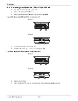
Страница 114: ...riple filters from the unit Figure 9 8 Figure 9 8 Removing 3M Triple filters from indoor unit 4 Clean the filters with a vacuum cleaner 5 Insert the 3M and or Triple filters in the unit Figure 9 9 Figure 9 9 Replacing 3M Triple filters in the indoor unit 6 Replace the air filters 7 Check the sides of the front cover to make sure the air filters are installed correctly Type1 Type2 Type1 Type2 ...

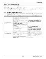
Страница 115: ...t service Water leaks from the indoor unit even when humidity level is low The power cable is damaged or it is generating excessive heat A switch circuit breaker safety ground or a fuse is not operating properly The unit generates and error code from self diagnosis Incorrect cabling Check the communication cable connections Incorrect scheduling setup Check the programmed Schedule settings The unit...

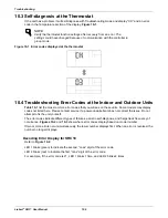
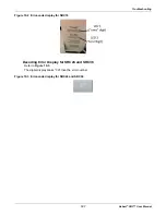
Страница 116: ...the unit yourself The error codes indicate different types of failures assist in self diagnosis and helps track frequency of occurrence Figures 10 2 and 10 3 show where error codes display based on model number If two or more errors occur simultaneously the lower number displays first When an error is resolved the number no longer displays Decoding Error Display for SRC18 Refer to Figure 10 2 LED ...

Страница 117: ...rt SRC User Manual Figure 10 2 Error code display for SRC18 Decoding Error Display for SRC24 and SRC36 Refer to Figure 10 3 The digital display blinks CH then the error number Figure 10 3 Error code display for SRC24 and SRC36 ...

Страница 118: ...eak IPM fault 1x 2x CH21 22 CT 2 Max CT 2x 2x CH22 23 DC Link Low High Volt 3x 2x CH23 26 DC Comp Position Error 6x 2x CH26 27 PSC Fault 7x 2x CH27 29 Comp Phase Over current 9x 2x CH29 32 Invert Compressor D pipe Overheat 2x 3x CH32 38 Refrigerant Leak detection 8x 3x CH38 37 Exceed the Compression Ration Limit 7x 3x CH37 41 D pipe Sensor Error 1x 4x CH41 44 Outdoor Air Sensor Error 4x 4x CH44 45...

Страница 119: ...annot adjust the temperature Select an operation mode in which you can adjust the temperature The unit stops during operation The unit is suddenly turned off The Timer Function may have timed out which turns the unit off Check the timer schedule settings A power failure has occurred during operation Wat for the power to come back If you have the Auto Restart function enabled your unit will resume ...

Страница 120: ...attention to areas such as basements etc where refrigerant cannot dissipate easily 3 Divide the refrigerant change of the Liebert SRC serving the area in pounds by the results of Step 1 The unit does not emit warm air When Heating Mode starts the vane is almost closed and no air comes out even thought the outdoor unit is operating This is normal Please wait until the unit has generated enough warm...

Страница 121: ... have limited mobility the allowable RCL limit is cut in half See ASHRAE Standard 34 2007 and local codes for detailed information 1 Figure 10 4 Refrigerant Concentration Limit RCL Calculations Equation 1 American Society of Heating Refrigeration and Air Conditioning Engineers Inc ASHRAE Atlanta GA ASHRAE Inc Information about ASHRAE Standard 15 2010 34 2010 and addenda current as of the date of t...

Страница 122: ...Troubleshooting Liebert SRC User Manual 112 Page intentionally left blank ...

Страница 123: ......

Страница 124: ...ove Di Sacco PD Italy 39 049 9719 111 Fax 39 049 5841 257 Asia 7 F Dah Sing Financial Centre 108 Gloucester Road Wanchai Hong Kong 852 2572220 Fax 852 28029250 While every precaution has been taken to ensure the accuracy and completeness of this literature Liebert Corporation assumes no responsibility and disclaims all liability for damages resulting from use of this information or for any errors ...

Отзывы: