SINUS-K
PROGRAMMING
MANUAL
203/
226
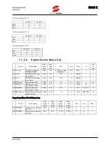
Note 02 State of digital outputs in the terminal board (1= active output) based on the table below:
bit
2 OC
3 RL1
4 RL2
Note 03 Operation time is represented by a double word (32 bits). It is sent using two addresses formatted as follows:
most significant word to higher address (1035); less significant word to lower address (1034).
Note 04 Fault list is sent using two addresses formatted as follows:
bit
15 8
7 0
Higher address (e.g.1037)
Alarm number
Time instant – bit 23÷16
Lower address (e.g.1036)
Time instant – bit 15÷0
Time instant relating to the alarm number is a 24–bit value with a 0.2s time base. Its most significant portion
(bits 23÷16) can be read in the lower byte of the word to the higher address, whereas its less significant portion (bits
15÷0) can be read in the word to the lower address.
The higher byte of the word to the higher address includes the alarm number coded as in Note 14 (inverter
state) (see Note 12).
The last alarm displayed in parameter M14 is the alarm with the longest time period. The other alarms are
displayed up to M18 with the shorter time period.
11.2.
PROGRAMMING PARAMETERS (Pxx) (Read/Write)
11.2.1.
R
AMPS
M
ENU
P0
X
–
P1
X
Name
Description
Addr.
(dec)
R/W
Addr.
(hex)
R/W
Def Min Max
K
Unit
of
meas.
P05 TAC1
Acceleration time 1
0
0
10
0.1
6500
10
s
P06 TDC1
Deceleration time 1
1
1
10
0.1
6500
10
s
P07 TAC2
Acceleration time 2
2
2
10
0.1
6500
10
s
P08 TDC2
Deceleration time 2
3
3
10
0.1
6500
10
s
P09 TAC3
Acceleration time 3
4
4
10
0.1
6500
10
s
P10 TDC3
Deceleration time 3
5
5
10
0.1
6500
10
s
P11 TAC4
Acceleration time 4
6
6
10
0.1
6500
10
s
P12 TDC4
Deceleration time 4
7
7
10
0.1
6500
10
s
P13 RAMP TH Ramp increase time
8
8
2
0
250
1
rpm
P14 RAMP EXT Ramp multiplicative factor
9
9
0
0
5
List
–
List for parameter P14:
0 1
1 2
2 4
3 8
4 16
5 32
V
T
C


