7
Instruction Manual IM02602008E - Rev. D
Transformer Temperature Controllers
IM02602008E - Rev. D May 2019 www.eaton.com
2.3 Bezel-Mounted Version
WARNING
TURN OFF AND LOCK OUT THE POWER SUPPLY
BEFORE WORKING IN ANY ELECTRICAL CABINET OR
TRANSFORMER CABINET. FAILURE TO DO SO COULD
RESULT IN INJURY OR DEATH FROM ELECTRICAL
SHOCK.
Prepare the transformer cabinet to receive the bezel-mount-
ed version, as follows:
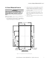
1. Cut a hole in the transformer cabinet to receive the TC
bezel-mounted version. See Figure 8, TC Bezel-Mounted
Cutout and Drill Dimensions, for dimensions.
2. Drill ten holes in the transformer cabinet to mount the
TC bezel-mounted version. See Figure 8, TC Bezel-
Mounted Cutout and Drill Dimensions, for dimensions.
3. Install the TC- bezel-mounted version into the cutout
hole, from the front.
4. Secure the TC unit to the transformer cabinet with
the 10 screws provided. Use moderate torque - 8 inch
pounds. Do not attempt to tap the holes. Do not use
machine screws.
5. The TC unit is now ready to be wired, from inside the
transformer cabinet.
Figure 8, TC - Bezel-Mounted Cutout and Drill Dimensions

