background image

38

Instruction Manual IM02602008E - Rev. D

Transformer Temperature  Controllers 


IM02602008E - Rev. D  May 2019   www.eaton.com

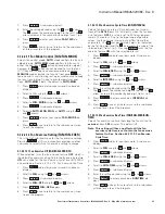
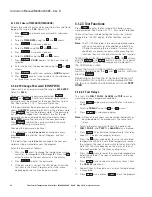
2.  Click the 

To Device

 check box to save this setting to the TC device when 

the 

Write

 function is selected.  

3.  Click 

Next

 or 

Previous

, or use the mouse, to select another configura-

tion category.

4.  When all configuration parameters have been changed/selected click 

Write

 to save all selected parameters to the TC device or click  

Save

 or 

Save As 

 to store this configuration as a file on the laptop for later use. 

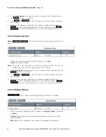
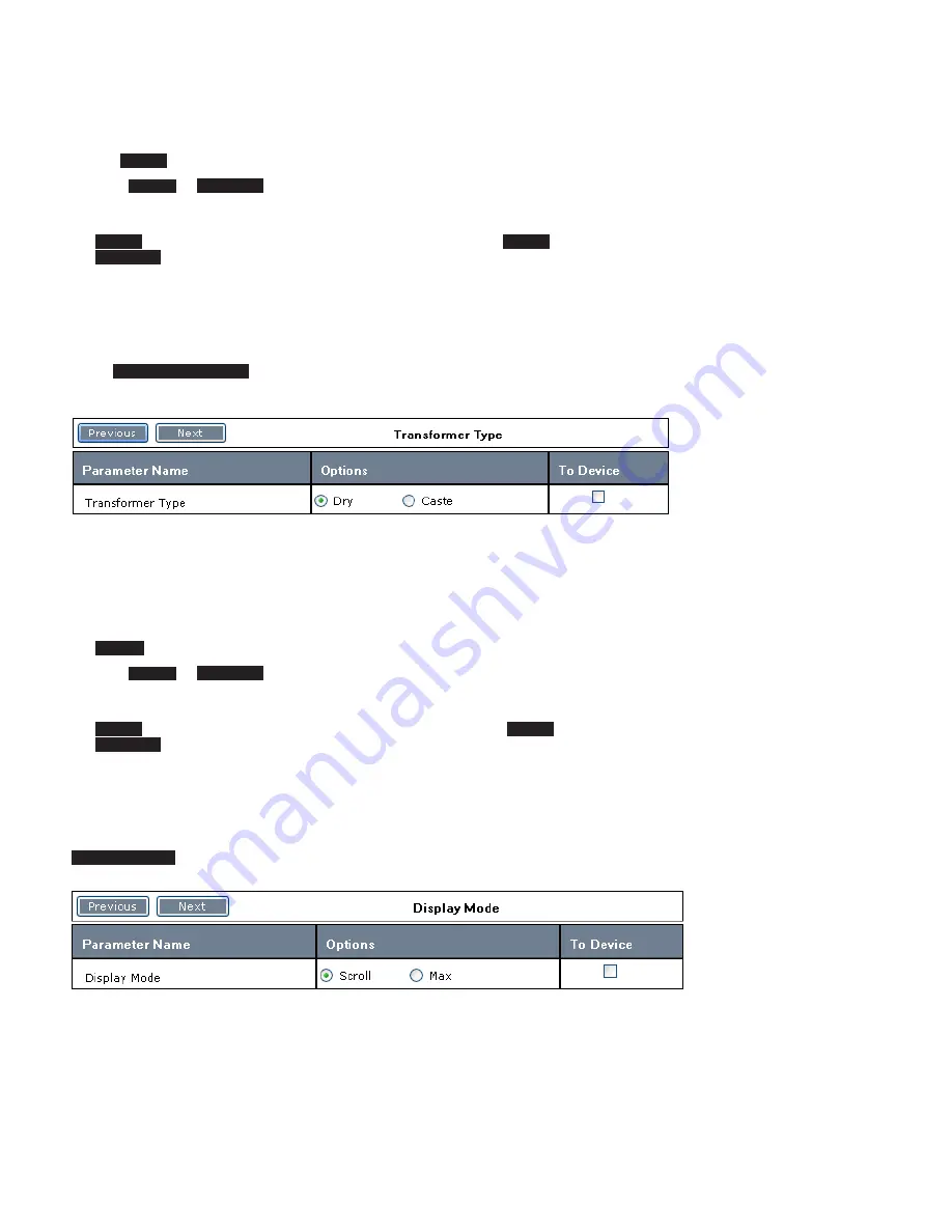
4.2.4.1.2 Transformer Type 

Select


Transformer Type

. The Transformer Type configuration parameters will 

appear.

1.  Select the transformer type desired. The options are 

Dry

 or  

Caste

. The default is 

Dry

.

otee:

N

This option is for reference only. It does not change any fan, alarm, or trip 

setpoint, or in any way alter operation of the TC device

2.  Click the 

To Device

 check box to save this setting to the TC device when the 

Write

 function is selected.   

3.  Click 

Next

 or 

Previous

, or use the mouse, to select another configura-

tion category. 

4.  When all configuration parameters have been changed/selected click 

Write

 to save all selected parameters to the TC device, or click  

Save

 or 

Save As 

 to store this configuration as a file on the laptop for later use. 

4.2.4.1.3

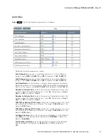
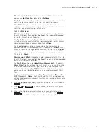
 Display Mode 


Display Mode 

. The Display Mode configuration parameters will appear.

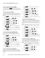
1.  Select the display mode desired. The options are 

Scroll

 or 

Max

. The default 

is 

Scroll

Scroll

 displays individual thermocouple temperatures sequentially, every 

three seconds. 

Max

 displays only the highest (maximum) thermocouple temperature

Содержание TC-50 Modbus

Страница 1: ...Instruction Manual IM02602008E Rev D Transformer Temperature Controllers...

Страница 2: ...recommendations descriptions and safety notations in this docu ment are based on Eaton Electrical Inc and or Eaton Corporation s Eaton experi ence and judgment and may not cover all contingencies If f...

Страница 3: ...3 TC Controller Unit 5 1 6 4 Equipment Testing 5 2 INSTALLATION 5 2 1 Preparation for Installation 5 2 1 1 General 5 2 2 Barrier Cabinet Version 6 2 3 Bezel Mounted Version 7 2 4 Wiring the TC Temper...

Страница 4: ...1 4 3 1 Introduction 71 4 3 2 Features 71 4 3 3 Hardware Installation 71 4 3 4 Connectors 71 4 3 5 Modbus Troubleshooting 72 5 POWER UP FOR TESTING 72 5 1 General 72 6 MAINTENANCE AND REPAIR 73 6 1 Pr...

Страница 5: ...rator The panel consists of an 9 character LED display 9 discrete LEDs and 9 pushbuttons Communication is also possible using a laptop computer connected to a front USB port or through Modbus on the T...

Страница 6: ...the front panel mounted to the door of the enclosure is exposed The front panel of the TC is shown in Figure 2 TC Front Panel This front panel provides the user interface to moni tor program and repo...

Страница 7: ...D CAUSE EQUIPMENT DAMAGE IMPORTANT THIS SYMBOL RELATES TO INFORMATION THAT IS IMPORTANT TO THE READER BUT IS NOT CLASSIFIED AS A VOLTAGE WARNING A GENERAL WARNING OR A CAUTION 1 4 2 General Safety Pre...

Страница 8: ...lush Mounting TC 100 Controller with Barrier Cabinet Hinged Front Panel TC 101 Cabinet Door forTC 50 or TC 100 Retrofit Applications TC Door Barrier Cabinet TC Barrier 1 6 Product Labels Every TC prod...

Страница 9: ...n 2 4 Wiring the TC for locations 2 Installation WARNING INSTALLING A TC TRANSFORMER TEMPERATURE CONTROLLER THAT IS IMPROPERLY RATED FOR THE ELECTRICAL SYSTEM VOLTAGE COULD CREATE A POTENTIALLY HAZARD...

Страница 10: ...imensions 3 Open the hinged panel on the TC to expose the barrier cabinet 4 Remove knock outs in the barrier cabinet as required and install cable clamps or grommets to secure and protect the wiring 5...

Страница 11: ...t to receive the TC bezel mounted version See Figure 8 TC Bezel Mounted Cutout and Drill Dimensions for dimensions 2 Drill ten holes in the transformer cabinet to mount the TC bezel mounted version Se...

Страница 12: ...Input Wiring shows alter native approaches for discrete input wiring TC 100 only 2 4 2 Wiring Procedures Follow these procedures to wire all TC models 2 4 2 1 Thermocouples 1 Connect the thermocouple...

Страница 13: ...ut circuits are isolated from the other cir cuits in the TC and have their own common connection Terminal 12 The contact signals are connected to Terminals 11 and 13 Two methods of powering and connec...

Страница 14: ...r to the fan s to terminal 4 Note N The fuses built into the TC 100 are standard 1 4 x 1 1 4 250 Vac 20 Amps maximum rating Lower rat ings may be used as required based upon the appli cation s power s...

Страница 15: ...TE INPUT 1 11 DISCRETE COM 12 DISCRETE INPUT 2 13 Transformer Temperature Controller 1 2 3 4 NEUTRAL INPUT POWER INPUT NEUTRAL OUTPUT FUSED POWER OUTPUT FAN 1 ALARM N C 1 LEFT PHASE CENTER PHASE RIGHT...

Страница 16: ...RYING GND CUSTOMER REMOTE INPUT CONTACTS OR PUSHBUTTONS TRANSFORMER CONTROL POWER TRANSFORMER CONTROL POWER CUSTOMER REMOTE OR PUSHBUTTONS INPUT CONTACTS REMOTE CONTACT WETTING SUPPLY 100 240 VAC 2 3...

Страница 17: ...to modify fan turn on alarm and trip conditions setting parameters for gathering report information and controlling various functions on a programmable timed basis The TC models can also be programmed...

Страница 18: ...panel requires a thorough understanding of the controls and how they are used to set up program the controller These controls are used to set up various operating parameters change setpoints reset al...

Страница 19: ...he Max mode you can scroll through the phase winding temperatures using the and arrows on the front panel After a 60 second time out the system returns to the Max mode 4 1 1 2 LED Indicators 4 1 1 2 1...

Страница 20: ...rmal Block out of range 4 1 1 3 Pushbutton Controls 4 1 1 3 1 Password Protection Three pushbuttons are password protected Reset Prog and Test A valid four character alpha numeric password must be ent...

Страница 21: ...date of the alarm and the tempera ture for each thermocouple at the time of the alarm The TC stores data for up to 25 alarms Temperature Trend data TC 100 only includes tem peratures at selected prog...

Страница 22: ...d function is displayed Then press Reset The function will be reset The LED Display will show RST COMP Press Reset to return to normal operation Press Back once to return to the Reset menu and twice t...

Страница 23: ...shows RST COMP 4 Press Back once to return to the Reset menu and twice to exit program 4 1 2 1 7 Reset All Logs Resets all Trend Alarm and Trip log data Note N This will delete all historical log dat...

Страница 24: ...us DEGREE C or Fahrenheit DEGREE F Default is DEGREE C 1 Press Prog and enter your password A sub menu will display 2 Scroll to TEMP C F using the and arrows 3 Press Select A sub menu displays 4 Scrol...

Страница 25: ...t the program 4 1 2 2 6 Input Channel Parameters INPUT CH This is the top level menu for setting the various thermo couple input channel parameters Pressing Select at this menu item to view a set of s...

Страница 26: ...ram 4 1 2 2 6 6 Input 4 INPUT CH CH ON or OFF INPUT4 Sets thermocouple On Off control for input to ON or OFF The default is ON Press Prog and enter your password A sub menu dis plays 1 Scroll to INPUT...

Страница 27: ...using the and arrows 5 Press Select A sub menu displays 6 Scroll to FAN 1 STP using the and arrows 7 Press Select A sub menu displays 8 Enter the temperature desired using the and arrows 9 Press Selec...

Страница 28: ...FAN 2 ACT dis plays 10 Press Back once or twice to return to the sub menus or three times to exit the program 4 1 2 2 10 Fan Wear Limit Settings FAN FAN WEAR TC 100 Only This is the first sub level me...

Страница 29: ...oll to FAN using the and arrows 3 Press Select A sub menu displays 4 Scroll to FAN OFF using the and arrows 5 Press Select FAN XER displays 6 Press Back once to return to the sub menu or twice to exit...

Страница 30: ...m Relay Fail Safe mode between ON and OFF On means Alarm Relay is powered when no alarms are active Off means Alarm Relay is not active The default is OFF 1 Press Prog and enter your password A sub me...

Страница 31: ...d arrows 5 Press Select A sub menu displays 6 Scroll to the selection desired STEADY or INTRMTNT using the and arrows 7 Press Select to enter your choice B TONE displays 8 Press Back once to return to...

Страница 32: ...e logging of trend data Pressing Select at this menu item provides a set of choic es for setting the time interval including MINUTES HOUR DAY or OFF The default is HOUR Note N Only one time increment...

Страница 33: ...FAIL TC 100 Only Configures discrete input 1 for use as a fan fail detector This may be used with an airflow sensor or micro switch connected to ventilation louvers to indicate when the fan is operat...

Страница 34: ...etpoints thus they can be used to always force fans On or Off 1 Press Prog and enter your password A sub menu displays 2 Scroll to D INPUT 2 using the and arrows 3 Press Select A sub menu displays 4 S...

Страница 35: ...he and arrows 7 Press Select XX M displays for the day currently selected 8 Enter the month of the year desired using the and arrows 9 Press Select to enter your selection MONTH dis plays 10 Press Bac...

Страница 36: ...the Reset Program or Test sub menu depending on the function being accessed 4 1 2 3 Test Functions Press Test to enter the Test mode This button is pass word protected See Section 4 1 1 3 1 Password...

Страница 37: ...ays 4 Press Back once to select another item from the Test sub menu 5 Press Back again or press Test to exit the pro gram 4 1 2 3 4 Test Buttons This test verifies that all front panel interface butto...

Страница 38: ...anized and how commands are entered To open the TC Series software program click the TC Series icon on the desktop or click All Programs then select the TC Series Transformer Wellness program from lis...

Страница 39: ...escribed in Section 4 2 3 Navigating the Options Bars 4 2 2 1 Model Indicator The upper right hand corner of the screen shown in Figure 13 shows what model is plugged in TC 50 TC 50 Modbus or TC 100 o...

Страница 40: ...Save As Saves the current configuration file to a PC file whose name and location is specified by the user Read Reads the configuration parameters from a connected TC device Write Writes the selected...

Страница 41: ...he Select All Parameters check box above the drop down menu then click the Write icon Parameters not changed will be written as well 3 Click Next or Previous to select the next or previous parameter c...

Страница 42: ...Caste The default is Dry Note N This option is for reference only It does not change any fan alarm or trip setpoint or in any way alter operation of the TC device 2 Click the To Device check box to sa...

Страница 43: ...ible alarm options desired The options relate to the audible alarm activation and tone Buzzer defines when the audible alarm comes On The options are Off Trigger on Alarm Trigger on Trip or Any The de...

Страница 44: ...nd Data Interval The Trend Data Interval configuration parameters will appear 1 Select the Trend time interval for logging trend data or disabling the logging of data as follows Trend Time Setting set...

Страница 45: ...d time read from the TC device when the Read button was clicked Note N The Set Current Date Time option is available when an existing con figuration is Open from a laptop file or when the configuratio...

Страница 46: ...ion alarm The options are On or Off This alarm activates when a transformer thermocouple temperature Inputs 1 2 or 3 is more than 30 C 54 F below the internal controller temperature Note N In some ins...

Страница 47: ...er of temperature inputs that must be above the setpoint before Fan 1 turns On The options are Any 1 Any 2 or All The default is Any 1 Number to Activate Fan 2 selects the number of temperature inputs...

Страница 48: ...eresis amount the temperature must drop below the setpoint for the alarm deactivation on return from an over temper ature condition The range is from 5 20 C 9 36 F The default is 5 C 9 F Alarm Fail Sa...

Страница 49: ...y is powered when no trip condition is pres ent Off means the Trip Relay is powered when one or more trip condi tions are present The default is On Trip Latch selects the trip relay latch mode between...

Страница 50: ...This allows connection to either normally closed or normally open contacts The default is Open For User Defined two options are given to define the relationship between the input state and output sta...

Страница 51: ...on the output or Invert which means an open on the input causes a closure on the output This allows the use of normally open or normally closed contacts on the input The default is Direct Discrete Inp...

Страница 52: ...t Report Viewer WinForms is not a configuration file If you try to open this directory an Error message will appear in the Messages Box 4 Click Cancel to cancel the operation 4 2 4 3 Save The Save opt...

Страница 53: ...to cancel the operation 4 2 4 4 Save As The Save As function allows you to save the current configuration to a file on the PC or network with the name and location specified by the user Select Save A...

Страница 54: ...urrent configuration to a connected TC device There is no associated sub menu Note N Prior to selecting the Write option ensure that the TC device is properly con nected to the laptop with a USB cable...

Страница 55: ...e open configuration file will be displayed behind the dialog box as shown at the end of this section To print the current configuration 1 Select the printer desired if more than one printer is availa...

Страница 56: ...52 Instruction Manual IM02602008E Rev D Transformer Temperature Controllers IM02602008E Rev D May 2019 www eaton com...

Страница 57: ...es feature upgrade capability for the TC 50 and TC 50 Modbus devices This option is not displayed on for the TC 100 because no feature upgrades are possible for this device 4 2 5 1 Trend Log Data TC 1...

Страница 58: ...in the upper right corner of the TC 100 Transformer Wellness software screen applica tion is On 4 Click Collect Data to collect the data specified from the TC 100 The Messages box will display each d...

Страница 59: ...layed on the TC device character display during this sequence to verify a successful upgrade After a successful upgrade the message Upgrade Firmware complete should appear in the messages box of the T...

Страница 60: ...ly connected to the laptop with a USB cable and the Online indication in the upper right corner of the TC device Transformer Wellness software screen is On 4 Click the Change box to execute the change...

Страница 61: ...ce The following dialog box appears 4 Click Yes to upgrade your device The following confirmation appears 5 Click OK to close the program 6 Restart the program to view your newly upgraded device The n...

Страница 62: ...iously downloaded from TC 100 units connected to the laptop For the most up to date reports connect to the desired TC 100 unit s and collect the latest data using the Trend Log Data option of the Devi...

Страница 63: ...on the calendar 8 Click the day of the month for the end date to select the end day 9 Click the Temperature Unit pull down menu to select the temperature unit for display The options are Celsius and...

Страница 64: ...ote N To return to the normal view click the curved arrow in the upper left hand corner of the screen If you hover the mouse pointer over this arrow the message will be Click here to go back to origin...

Страница 65: ...te 5 Click the End Date Time menu to display a calendar as shown above 6 Select the month for the end date desired by clicking the and arrows on the calendar 7 Click the day of the month for the end d...

Страница 66: ...wn menu 2 Click the Start Date Time menu to display a calendar as shown below 3 Select the month for the start date desired by clicking the and arrows on the calendar 4 Click the day of the month to s...

Страница 67: ...w using the left and right arrow icons or you can scroll to the page desired using the scroll bar The report can be printed by clicking the Print icon or exported to Excel for more detailed analysis o...

Страница 68: ...The Start date must always be less than the End date 5 Select the month for the end date as described above 6 Click the day of the month for the end date to select the end day 7 Click Show Report to d...

Страница 69: ...right arrow icons or you can scroll to the page desired using the scroll bar The report can be printed by clicking the Print icon or exported to Excel for more detailed analysis or as an Acrobat PDF...

Страница 70: ...heck box for the type of Tend Logs data you want to delete for the time period selected All Deletes the Trend Data Alarm Log and Trip Log Note N Deleting all data for a particular transformer will als...

Страница 71: ...available are shown in the left pane They include TC Series Configuration Device Reports and Calibration 2 Click the plus sign for the help category desired to display an expanded list of subjects suc...

Страница 72: ...ys the subjects overed on the function bar Click Contents to display the subjects covered on the function bar This menu is shown in the collapsed view noted by the plus sign to the left of each topic...

Страница 73: ...ature Controllers IM02602008E Rev D May 2019 www eaton com 4 2 8 2 Index Tab The Index tab option lists all parameters in alphabetical order Click Index to display all parameters Click a subject to ob...

Страница 74: ...you to search for a file by name Click Search to display the Search dialog box 1 Enter the topic desired in the Display Topic window or select the topic from a list by clicking the pull down menu arr...

Страница 75: ...C 100 models provide a half duplex EIA RS 485 network connection EIA RS 485 is a multi drop industrial grade communications standard It is a balanced differential signal that feeds over a twist ed pai...

Страница 76: ...ectly from the master to the Modbus slave device Verify that the network is terminated properly Modbus RX LED and TX LED are flashing but the TC 50 Modbus or TC 100 responds with error codes to master...

Страница 77: ...replaced 6 3 Controller Replacement Remove and replace the TC controller as follows 1 Lock Out and Tagout the transformer and the TC unit serving it 2 Access the controller by opening the hinged panel...

Страница 78: ...thermocouple if broken If this is a typical operating condition disable reverse thermocouple detection Display shows A OVRTMP Winding temperature s exceed Alarm threshold Verify proper alarm setpoint...

Страница 79: ...C one count under extreme conditions Extreme conditions are Ambient temperature colder than 10 C Winding to unit temperature greater than 210 C Discrete Inputs Number of Inputs Two 2 programmable Rat...
Страница 80: ...CISPR 11 Class A CFR 47 FCC Part 15 Subpart B Class A Clock Accuracy 1 minute month 25 C Backup 30 days with no control power Logging Trend Data 100 entries logging interval programmable from 1 minut...

Страница 81: ...iguration Parameters Parameter Name Front Panel Display Name Default Value Range Description Display Mode DISPMODE Scroll Scroll Max Controls front panel display to scroll through all measurements or...

Страница 82: ...oth FAN Exercise Cycle Time FAN INTERVAL Off Off 0 01 30 days Fan exercise interval time between fan turn on FAN Exercise Run Time FAN RUN TIME 1 1 120 minutes Fan exercise run time Alarm Setpoint ALA...

Страница 83: ...ONTH 1 1 12 Set the current month for alarm and trip history and trend logging Day TIME DATE DATE DAY 1 1 31 Set the current day for alarm and trip his tory and trend logging Hours TIME DATE TIME HOUR...

Страница 84: ...3 40009 9 Read Only Winding 3 Temperature 0 255 C or F 2 3 40010 A Read Only Ambient Temperature 0 255 C or F 2 3 40011 B Read Only Max Temperature 0 255 C or F 2 3 40012 C Read Only Average Temperat...

Страница 85: ...ite Only Parameters Function Code Register Address Decimal Register Address Hex Register Type Parameter Description Data Range Number of Bytes 6 16 40033 21 Write Only FAN Control 1 toggles ON OFF 2 6...

Страница 86: ...uple Type 0 K 1 E 2 3 6 16 40111 6F Read Write Reverse Detection 0 OFF 1 ON 2 3 6 16 40112 70 Read Write FAN 1 Setpoint in Fahrenheit 32 482 OFF 0x0FFF 2 3 6 16 40113 71 Read Write FAN 2 Setpoint in F...

Страница 87: ...and in Fahrenheit 41 68 2 3 6 16 40129 81 Read Write Trip Fail Safe 0 OFF 1 ON 2 3 6 16 40130 82 Read Write Trip Latch 0 OFF 1 ON 2 3 6 16 40131 83 Read Write Buzzer 0 OFF 1 Trigger on Alarm 2 Trigger...

Страница 88: ...n2 4 Alarm 5 Trip 6 Fan2 7 Fans ON 8 Fans OFF 2 3 6 16 40141 8D Read Write RTC_Year 2000 3000 2 3 6 16 40142 8E Read Write RTC_Month 1 12 2 3 6 16 40143 8F Read Write RTC_Day 1 31 2 3 6 16 40144 90 Re...

Страница 89: ...ta format for this log is detailed below 16 Bytes 8 Registers Per Each Record 25 Records Max 3 41101 41108 41109 41116 41293 41300 44D 454 455 45C 50D 514 Read Only Alarm Log Alarm Log 16 Bytes 8 Regi...

Страница 90: ...000 3000 16 Record Separator 255 Alarm Log Format Byte Number Description Data Range 1 Series Number 1 25 2 3 Alarm Event bit 0 1 Over Temperature bit 1 1 Air Flow not Detected TC 100 only bit 2 1 Tem...

Страница 91: ...87 Instruction Manual IM02602008E Rev D Transformer Temperature Controllers IM02602008E Rev D May 2019 www eaton com Notes...

Страница 92: ...Township PA 15108 4123 USA 877 ETN CARE 1 877 386 2273 www Eaton com 2019 Eaton All Rights Reserved Printed in USA Publication No IM02602008E Rev D Style No 66A2454H01 TBG 001453 May 2019 Eaton is a...

Отзывы: