72
Instruction Manual IM02602008E - Rev. D
Transformer Temperature Controllers
IM02602008E - Rev. D May 2019 www.eaton.com
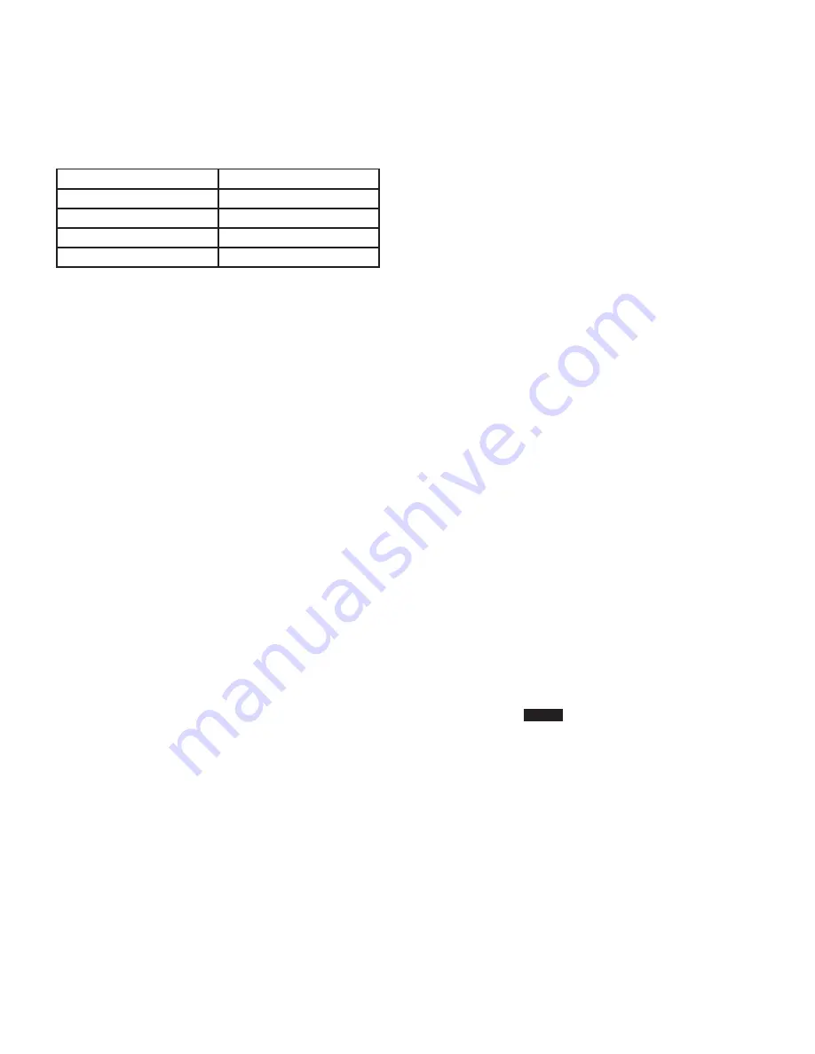
Table 2, below, shows the 5-pin connector pin-out assign-
ment.
Table 2 - Modbus Pin-Out Assignment
Pin
Signal
1
A (-)
2
B (+)
3
Common
4
Shield
4.3.4.2 Wiring Notes
For maximum noise immunity, the shield of the RS-485
cable should be daisy-chained from one slave device to
another and terminated to chassis ground at the Modbus
master-end of the network (single-point ground).
4.3.4.3 System Capacity
The address of the TC-50 Modbus or TC-100 can be set
between 1 and 247 (decimal) allowing to operate on net-
works containing up to 247 TC-50 Modbus or TC-100 units
or other slave devices.
4.3.4.4 LEDs
4.3.4.4.1 Red RS-485 Transmit LED (TX) Indicator
The RX LED on the TC-100 or TC-50 Modbus controller turns
on when the TC-100 is responding to a request. The TC-50
Modbus and TC-100 models only respond to requests to its
address.
4.3.4.4.2 Red RS-485 Receive LED (RX) Indicator
The RX LED flashes when the TC-100 or TC-50-Modbus
detects that a signal is being received. The LED flashes
even if the signal is at the wrong baud rate, to a different
adddress, etc.
4.3.5 Modbus Troubleshooting
The most common issues experienced with the operation
of the TC-50 Modbus and TC-100 on a Modbus network are
addresssed as follows:
•
Modbus RX LED and TX LED do not light:
* Verify that the communication cable is connected cor-
rectly from the master to the Modbus slave device.
•
Modbus RX LED is flashing, but the TC-50 Modbus or
TC-100 does not respond to master command requests.
* Verify that the baud rate, parity, number of stop
bits, and address are correctly set using the front panel
keypad (see Section 4.1.2.2.4.2, Parity) or with the PC
software (Section 4.2.4.1.5, Modbus).
* Verify that the communication cable is connected cor-
rectly from the master to the Modbus slave device.
* Verify that the network is terminated properly.
•
Modbus RX LED and TX LED are flashing, but the TC-50
Modbus or TC-100 responds with error codes to master
command requests.
* Verify that the function code, register address, and
data value in the command from the master are
valid per the register map in Appendix B.
* If the command request is valid, verify that the TC-50
Modbus or TC-100 is properly connected to chassis
ground, that the cable shield is connected to chassis
ground only at the master, and that the network is
terminated properly.
If you have any questions or need further information or
instructions, contact the Eaton Technical Support Center at
1-800-809-2772.
5. Power Up for Testing
5.1 General
After the TC has be installed, wired properly, and pro-
grammed, it must be tested prior to placing it in service.
Test the TC models as follows:
•
Ensure all control power and fan power wiring is sized
and fused properly. Ensure all signal and control wiring is
properly segregated from power wiring within the trans-
former cabinet. Ensure all wiring within the barrier cabinet
is secured to avoid excessive strain when the frontcover
is closed..
•
Apply control power to the unit and verify the power-on
self test completes and the unit displays proper tempera-
tures for the connected thermocouples.
•
Use the front panel
Prog
button or PC Application
to configure any necessary parameters. At the very
least the current date/time should be verified/set. If the
Modbus interface is to be used its configuration should
also be verified/set.
•
Use the front panel Test button to enter test mode and
turn on the individual relays to verify their wiring. Also
verify that all of the buttons and LEDs operate properly
and verify that the internal temperature is correct.
•
If discrete inputs are used verify that open/closed con-
tacts provide the desired response.
•
If the 4-20mA output is used, verify that the remote
monitor is indicating the correct maximum winding tem-
perature.


