


RS4203 Manual
Chapter 10 - Clipper and Looper Operation and Adjustments
Rev 32, 01/11/13
Copyright © 2013, Tipper Tie, Inc., All rights reserved
69
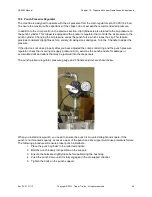
Feed casing onto the horn and pull it through the voiders. Then, push the clip and loop button. This will
feed the first loop into the die support. The machine is ready to start running product.
When the machine first runs, watch the looper closely, keeping an eye on where the loop knot is
positioned. You may have to adjust the knot location so that it stops just short of the loop door.
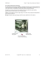
If the loop knot stops too far away from the loop door, the loop may not be feeding far enough for the knot
door to catch the knot. This will cause the loop to pull out of the die support when the clipper swings out
to the clip position.
If the loop knot stops too close to the loop door, when the clipper swings in, the loop knot may deflect off
the loop door. This will cause the loop knot to be pushed away from the center of the die support loop
window, and the loop may misfeed.
Note: The air blast may straighten the knot out and push it into the loop window, but occasional misfeeds
may occur if the loop knot position is not correct.
10.8.2 Looper Settings and Adjustments
This section provides detailed instructions on looper system setup and adjustments.
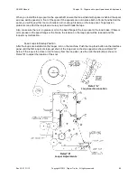
Location of Loop Insertion Into the Die Support
Adjust the looper so that it feeds the loop into the die support loop window as shown in Detail “A” on the
previous page.
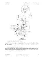
Raising and Lowering the Looper
To raise or lower the looper, referring to Detail “B” on the previous page, loosen bolt
A
and the nut on bolt
B
. The nut on bolt
B
is located on the back side of the looper assembly. Loosen the lock nut on the jack
bolt
C
. Turn jack bolt
C
clockwise
to raise the looper or
counterclockwise
to lower the looper. When the
looper is in the correct position, tighten the nut on jack bolt
C
, and tighten bolt
A
and the nut on bolt
B
.
Adjusting the Looper Forward and Backward
To adjust the looper forward and backward, loosen bolts
E
and
F
. This will allow the looper to pivot on
bolt
E
. Adjust the looper to the correct position as shown in Detail “A” on the previous page. Tighten bolts
E
and
F
.
Proper Looper Distance Between Die Support and Loop Insertion
The proper looper distance between the Clipper Die Support and the loop insertion is as follows: The loop
knot is being grabbed by the Upper and Lower Loop Strip Plates near the center or back end of the loop
knot, and the loop knot just misses the loop door, as shown in the lower right corner of Detail “B”.
Adjusting the Distance Between Looper and Clipper Die Support
Referring to Detail “B”, loosen bolt
A
and the nut on bolt
B
, which is located on the back side of the looper
assembly. This allows the looper to pivot on bolt
A
. Loosen the locking nut on jack bolt
D
. Turn jack bolt
D
clockwise
to move the looper away from the Clipper Die Support. Turn jack bolt D
counterclockwise
to
move the looper closer to the Clipper Die Support. When the looper is in the correct position, tighten the
nut on jack bolt
D
, and tighten bolt
A
and the nut on bolt
B
.


