Commissioning and Operation
- 156 -
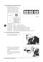
4.8.3. Method of adjusting the valve clearance
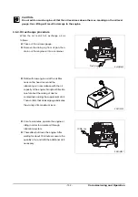
1) Loosen the lock-nuts (1) using a ring
spanner.
2) Insert a thickness gauge of 0.3 mm
between valve stem (2) and rocker arm (3).
3) Turn the adjusting bolts (4) using a screw
driver until the gauge can be pulled out
with some restriction.
4) After the adjustment fix the adjusting bolt
not to rotate and tighten the lock-nut at
the same time.
5) Measure the clearance one more time
and if necessary adjust again.
4.9. Ignition Timing
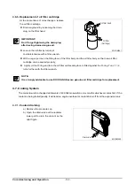
4.9.1. Ignition timing sensor
Move the lock nut to hexagonal side of
sensor completely.
Rotate (Clockwise) the timing sensor on
the coupling housing, until the end of it
reach on the timing drive gear.
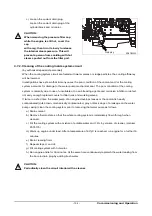
4.9.2. Adjustment of Ignition timing
Turn the flywheel until No. 1 piston is
placed in the "OT" position of notch
marks on the flywheel, and then turn
again the flywheel clockwise until
showing the notch mark of the right
figure corresponding to the ignition
timing is aligned with the pointer (
)
on the flywheel housing.
EAOO4014
4
1
3
2
ED4OM028
Ignition
timing sensor
Sensor gap
0.5 °
±
0.1
Flywheel
ring gear
Ignition timing mark
(Fly wheel)
Timing check hole
ED4OM043
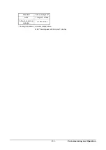
Model
GL08K
Ignition timing
(B.T.D.C static)
10°
Содержание GL08K
Страница 1: ...950106 050004EN GL08K GAS VEHICLE ENGINE Operation Maintenance Manual ...
Страница 2: ......
Страница 4: ......
Страница 6: ......
Страница 151: ...Maintenance 145 7 Vehicle wiring harness EH3M5012 Truck engine Bus engine ...
Страница 193: ...Appendix 187 Engine Assembly Bus EJ3OM012 ...
Страница 194: ...Appendix 188 Engine Assembly Truck EJ3OM013 ...
Страница 195: ...Special Tool List 950106 080002 ...
Страница 196: ......

