background image

950106-050004EN

GL08K

GAS VEHICLE ENGINE

Operation &
Maintenance Manual

Содержание GL08K

Страница 1: ...950106 050004EN GL08K GAS VEHICLE ENGINE Operation Maintenance Manual ...

Страница 2: ......

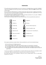
Страница 3: ...rtant Reassembly Tighten to specified torque Align the marks Use special tools of manufacturer s Directional Indication Lubricate with oil Inspection Lubricate with grease Measurement During engine maintenance please observe following instructions to prevent environmental damage Take old oil to an old oil disposal point only Ensure without fail that oil and coolant will not get into the sea or riv...

Страница 4: ......

Страница 5: ...rts 61 3 3 Engine Reassembly 79 3 4 Major Electric Parts Replacement 104 3 5 Electrical System 116 4 Commissioning and Operation 148 4 1 Operation Preparation 148 4 2 Breaking in 148 4 3 Inspections after Starting 150 4 4 Operation in Winter Time 150 4 5 Tuning the Engine 151 4 6 Maintenance and Care 151 4 7 Cooling System 153 4 8 Adjustment of Valve Clearance 155 4 9 Ignition Timing 156 4 10 Tigh...

Страница 6: ......

Страница 7: ...tc consult a doctor immediately 1 1 2 To prevent accidents with injury to persons 1 Engine starting and operation Before putting the engine into operation for the first time read the operating instructions carefully and familiarize yourself with the critical points If you are unsure ask your DOOSAN representative or service man For reason of safety we recommend you attach a notice to the door of t...

Страница 8: ...e Do not smoke or use naked lights in its vicinity The tank must be filled only when the engine is switched off Keep service products anti freeze only in containers which can not be confused with drinks containers Comply with the manufacturer s instructions when handling batteries CAUTION Accumulator acid is toxic and caustic Battery gases are explosive Therefore it should be done by an expert of ...

Страница 9: ...ngine maintained at the specified intervals Do not switch off the engine immediately when it is warm but let it run without load for about 5 minutes so that temperature equalization can take place Never put cold coolant into an overheated engine Do not add so much engine oil that the oil level rises above the max marking on the dipstick Do not exceed the maximum permissible tilt of the engine Alwa...

Страница 10: ...t engine oil get into the ground waterways the drains or the sewers Violations are punishable Collect and dispose of used engine oil carefully For information on collection points please contact the seller the supplier or the local authorities 1 1 6 Precaution for handling NOx clean NOx clean is a solution diluted to the regulated ratio Manufacturing method is standardized through standards 1 As a...

Страница 11: ... care as they cause paint damage 4 The use of proper tools and special tools where specified is important to efficient and reliable service operation 5 Use genuine DOOSAN parts necessarily 6 Used cotter pins gaskets O rings oil seals lock washer and self lock nuts should be discarded and new ones should be prepared for installation as normal function of the parts can not be maintained if these par...

Страница 12: ... operable engine to relieve natural gas pressure To avoid personal injury an operable natural gas engine must be kept in a well ventilated area away from open flames and sparks If the engine can run use the following venting procedure to relive the natural gas pressure downstream of the shutoff valve 1 Shut off manual valves on natural gas supply tanks and main shutoff valve on natural gas fuel su...

Страница 13: ...ear pressurized fluid lines Wear welding goggles and gloves when welding or using an acetylene torch Insure a that metal shield separated the acetylene and oxygen which must be chained to a cart Do not weld or heat areas near fuel tanks or fuel lines HDO1049I ...

Страница 14: ...Rotating direction from flywheel Counter clockwise Firing order 1 5 3 6 2 4 Fuel ignition timing B T D C static 10 1 Engine control system ECM Engine control module type Compression pressure kg cm2 16 at 200 rpm Valve clearance Intake valve 0 3 Exhaust valve 0 3 Intake valve Open at 16 B T D C Close at 36 A B D C Exhaust valve Open at 46 B B D C Close at 14 A T D C Lubrication method Full forced p...

Страница 15: ...pack coil on plug Spark Plug Double platinum electrode Spark Plug Gap mm 0 39 0 4 Ignition Type Coil on plug type Ignition Timing Controlled by ECM and ICM not user adjustable Control System Control system On highway heavy duty CNG engine control system Voltage V 24 Component ECM ICM sensors wire harness Air Compressor Cooling method Water cooled Driving method Belt driven Turbocharger Model Holse...

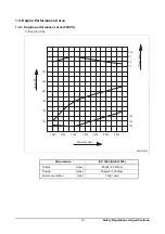
Страница 16: ...ormance curve 240PS 1 Bus 240 PS Performance ISO 1585 SAE J1349 Output max 240ps 2 300rpm Torque max 90kg m 1 400rpm Fuel consumption min 140g ps h EJ3OM001 1 400 100 140 1 000 180 220 260 1 200 1 600 1 800 2 000 2 200 90 100 80 70 300 150 145 140 kg m Torque Revolution rpm Output PS ...

Страница 17: ...S Performance ISO 1585 SAE J1349 Output max 260ps 2 300rpm Torque max 100kg m 1 400rpm Fuel consumption min 138g ps h EJ3OM002 0 100 1 400 1 000 1 200 1 600 1 800 2 200 2 000 140 150 300 200 70 90 110 80 100 130 800 kg m Torque Revolution rpm Output PS ...

Страница 18: ...ft 4 Intake valve 16 Oil seal rear 5 Exhaust valve 17 Oil seal rear 6 Intake valve spring 18 Crank shaft pulley 7 Breather 19 Crank gear 8 Exhaust valve spring 20 Vibration damper 9 Cylinder head cover 21 Oil pump 10 Cylinder head 22 Oil suction pipe 11 Cylinder block 23 Oil pan 12 Push rod 24 Crank shaft 1 2 3 4 5 6 7 8 9 10 11 12 13 14 15 16 17 18 19 20 21 22 23 24 EB8O1003 ...

Страница 19: ...al view cross 1 Oil filter 7 Spark plug 2 Oil spray nozzle 8 Rocker arm 3 Connecting rod 9 Rocker arm bracket 4 Oil filler cap 10 Exhaust manifold 5 Idle pulley air compressor 11 Turbo charger 6 Ignition coil 12 Oil cooler 5 4 3 2 1 6 7 8 9 10 11 12 ED4OM051 ...

Страница 20: ...ngine mounting bracket 5 Air pipe Turbocharger Intercooler 15 Oil filter 25 Oil coller 6 Air compressor 16 Idle pulley 26 Starter 7 Power steering pump 17 Thermostat 27 Ignition coil 8 Ignition timing sensor 18 Cooling water pump 28 Cooling water temperature sensor 9 Oil filler 19 Turbocharger 29 Intake manifold temperature pressure sensor 10 Oil level gauge 20 Solenoid valve Turbocharger 30 Pre t...

Страница 21: ...old 16 Gas pressure Gas temperature sensor 27 Starter 6 Throttle valve 17 Oil filter 28 Ignition coil 7 Air pipe Turbocharger Intercooler 18 Thermostat 29 Cooling water temperature sensor 8 Air compressor 19 Cooling water pump 30 Intake manifold temperature sensor 9 Power steering pump 20 Turbocharger 31 pre throttle pressure sensor 10 Ignition timing sensor 21 Solenoid valve turbocharger 32 Fuel ...

Страница 22: ...questing warranty and ordering parts They are also referred to as engine model and serial number because of their location Engine serial No example 1 GL08K Bus GL08K 1 00001 BA Engine model suffix ETPBA Serial no Production year 2011 Engine model Engine serial No example 2 GL08K Truck GL08K 1 00001 CA Engine model suffix ETPCA Serial no Production year 2011 Engine model EJ3OM005 Engine number ...

Страница 23: ...Air to air charge cooling Waste gated turbocharger with a water cooled bearing housing 2 3 1 Cylinder block The cylinder block is a single piece of alloy cast iron To increase its stiffness it is extended to a level below the crankshaft center line The engine has replaceable dry cylinder liners and individual cylinder heads with struck in valve seat rings and replaceable valve guides 2 3 2 Piston ...

Страница 24: ... train arranged at the front end 2 3 4 Valves The overhead valves are actuated via chilled cast iron tungsten carbide tappets push rods and rocker arms from the camshaft Ignition timing sensor gear Z 54 Camshaft gear Z 54 Oil pump drive gear Z 36 Idle gear Z 42 Crank shaft gear Z 27 Oil pump idle gear Z 23 ED4OM006 ...

Страница 25: ...and camshaft bearings as well as to the small end bearings and the rocker arms The turbocharger are also connected to the engine lubricating system The cylinder walls and timing gears are splash lubricated Each cylinder has an oil jet provided for cooling the underside of the pistons The lube oil is cleaned in a full flow oil filter ED4OM007 Turbo charger Air compressor Crank journal Rocker arm bu...

Страница 26: ...cted SAE No 15W40 The following oils are also recommended Use only Doosan Infracore recommended engine oil Engine Oil capacity First oil change After 1 000 km 50hr operating Short distance operation vehicle city bus truck every 20 000 km SAE No Sulfated ash content 15W40 Bellow 0 5 Engine oil capacity Engine model Vehicle Oil pan inside Total lit Max lit Min lit GL08K Bus ETPCA ETPBA 17 14 20 BEB0...

Страница 27: ...re and oil leaks and repair or replace the oil filter if necessary Change the oil filter cartridge simultaneously at every replacement of engine oil 2 3 9 Air cleaner In case that elements are deformed damaged or if the air cleaner has a crack replace it By the definite interval the elements must be cleaned and replaced ED4OM008 Oil cooler Cooling water outlet Cooling water inlet Oil filter head O...

Страница 28: ... valve open feeds fuel into the common fuel line With its shut off valve closed the tank doesn t feed the common line but the valve s tee is exposed to common line high pressure From there fuel flows to the fuel pressure regulator The pressure regulator drops fuel pressure to approximately 8bar From the regulator fuel flows to the fuel metering valve containing a low pressure shut off solenoid val...

Страница 29: ...eposits from electrode and Inspect insulator area Measure the spark plug distance at electrode position A Replace spark plug if necessary Install spark plug Standard Distance A 0 39 0 40 mm Torque 2 04 4 08 kg m A EB3O310I ED4OM056 New spark plug Electrode surfaces not parallel Eroded electrode Flashover on insulator ...

Страница 30: ...hout first removing the negative battery cable from the battery Denoxtronic Control Unit Do not perform remove the inner parts of the engine control module ECM 2 3 13 Ignition control module ICM A synchronization pulse index is also sent by the ECM to the ICM so that the ICM fires the correct coil CAUTION Do not perform remove the inner parts of the ignition control module ICM ECM J2 B J2 A J1 C J...

Страница 31: ...rning fuel and offers a low particulate emission Natural gas is also a very economical fuel From the gas producing areas in the country the distribution companies and local utilities from a complex nation wide delivery network that supplies natural gas for home and industry use The network is highly developed and extended to all major population center in the country Main harness Ignition harness ...

Страница 32: ... large cooling fan capacity The intercooler life and performance depends on the intake air condition greatly Fouled air pollutes and clogs the air fins of intercooler As a result of this the engine output is decreased and engine malfunction is occurred So you always check whether the intake air systems like air filter element are worn or polluted In order to maintain the heat transfer efficiency o...

Страница 33: ...xpansion tank by removing the expansion tank filler cap and add coolant if necessary When injecting antifreeze solution first drain out the old coolant from the cylinder block and radiator and then clean them with cleaning solution Be sure to mix soft water with antifreeze solution Thermostat Turbo charger Oil cooler R a d i a t o r Cooling water pipe Cylinder head Cylinder block Cooling water pum...

Страница 34: ...numbered block example if the color of NITRITE pad is between standard color D and F then use column E Since GL08K cylinder liner is dry type particularly the cooling water control should be applied thoroughly The density of antifreezing solution and additive for rust prevention is able to be confirmed by the cooling water test kit Fleetguard CC2602M or DOOSAN Infracore 60 99901 0038 How to use th...

Страница 35: ...the test paper storage bottle 7 In case of less than 0 3 replenish the additive for rust prevention DCA4 and in case of more than 0 8 pour out the cooling water about 50 and then readjust the density after refilling with clean fresh water Amount of Anti freeze in winter 2 3 21 Fan belt V belt Use a fan belt of specified dimensions and replace if damaged frayed or deteriorated Check the fan belt fo...

Страница 36: ...arance adjust it when in cold as follow By cranking the engine let 6 cylinder s valves overlap In time adjust the valve clearance corresponding to of lower lists Adjust the valve clearance corresponding to of lower lists After reinsuring the valve clearances retighten if necessary Adjust valve clearance with a feeler gauge and tighten the fixing nuts to specified torque No 1 Cylinder is located at...

Страница 37: ...ery crack and replace the ba tery in case of poor condition Inspect for amount of electrolytic solution and replenish if insufficient Measure the gravity of electrolytic solution if less than specif ied value 1 12 1 28 replenish Standard value 16 kg cm2 over Limit value 15 kg cm2 Difference between each cylinder Within 10 Ignition coil EJ3OM027 Cover Ignition coil EJ3OM028 Gauge adapter Compressio...

Страница 38: ... hand side As parts of every engine overhaul the starter pinion and ring gear should be cleaned with a brush dipped in fuel and then a coat of grease should be applied again EJ2OM006 Battery terminal Terminal switch 24V x 6 0kW Magnetic switch Starting motor Battery terminal Battery terminal Battery switch EI4OM023 M M S Wiring harness ...

Страница 39: ...Technical Information 33 Vietnam Specifications EGL0818007 Battery terminal M5 x P0 8 Terminal switch M10 x P1 5 24V x 6 0kW EGL0818008 Wiring harness B M M S S B S W ...

Страница 40: ...tage The alternator should not be operated except with the regulator and battery connected in circuit to avoid damage to the rectifier and regulator EJ3OM015 Battery ground Relay terminal Indicator light terminal M5 X 0 8 Battery terminal M6 X 1 0 M6 X 1 0 M5 X 0 8 28 5V x 80A 0 5 MFD to Battery Regulator Relay Phase Terminal Lamp Terminal Trio Diode Rectifier zener diode 37V 30A Rectifier trio di...

Страница 41: ...transistorized regulator mounted on the alternator body interior limits the alternator voltage The alternator should not be operated except with the regulator and battery connected in circuit to avoid damage to the rectifier and regulator EGL0818009 M8 x 1 25 M8 x 1 25 24V x 150A Battery Terminal E Terminal EGL0818004 0 5 MF B E E N F ...

Страница 42: ...uted Inspect air cleaner Nature gas fuel Inspect amount fuel Check compression pressure Inspect of other parts Check cylinder head gasket Inspection of battery electorlytic liquid amount gravity Inspection of loose electric wiring short Starting motor revolution Too low Adjustment Recharging Normal Retighten Replace Normal Repair Replace Normal Starting motor disassembly Normal Replace Engine disa...

Страница 43: ...w Check fan belt tension wear or damage etc Inspect cooling water leakage Normal Normal Normal Replace External Internal Engine disassembly Check fresh radiator tank cap Normal Normal Damage Normal Check cooling water pump Inspect radiator Replace Check thermostat Clean cooling water passage Engine disassembly Repair Replace Repair Replace Repair Replace Retighten Replace ...

Страница 44: ...ness Ignition coil spark plug boots etc Disassemble engine or ECM Disassemble engine or ECM Check turbocharger Normal Adjust Adjust Normal Replace Inspect cylinser head gasket for damage Engine disassembly valve assembly Check valve clearance Normal Inspect air leakage of air piping line Inspect air leakage of intercooler Normal Inspect air cleaner Adjust or replace clutch Retighten Replace Repair...

Страница 45: ...heck oil relief valve Water mixed in oil Improper Inspect oil quality Refer to engine overheat Too high Check cooling temperature Use recommened oil replenish Check if oil pressure gauge indicates wrongly Disassemble engine Disassemble engine Replace with recommended oil Normal Retighten Replace ...

Страница 46: ... Case according to use conditions 1 Overload 2 Frequence use of low gear position at high speed 3 Frequence use of high gear position at low speed 4 Clutch slip 5 Too low tire inflation pressure Normal Adjust Normal Inspect compressed pressure Disassemble engine vavle assembly piston cylinder liner etc Normal Adjust Repair replace cylinder liner pistion ring piston Retighten Replace ...

Страница 47: ...ve stem seal Check oil quality Clean Replace Confirm Unconfirmed Inspect compressed pressure Disassemble eingine Case according to use conditions 1 Excessive oil infusing 2 Continuous operation in low speed or extremely cold state Normal Normal Replace with specified oil Inspect high pressure pump Check fuel quality Check valve clearance and cylinder head gasket crush External Internal Normal Too ...

Страница 48: ...shorts and loose connections Check fan belt tension damage Battery room damage Replenish Repair Replace Replce Charging Inspect alternator voltage regulator Battery self dischage Battery over charging Electrolytic liquid s standard Normal Check charged stated Discharging Disassemble alternator Voltage regulator Abvormal Adjust Replace ...

Страница 49: ...engine Adjust Repair or replace Clean or replace air cleaner 4 Overheating Engine oil insufficient or poor Cooling water insufficient Fan belt loosened worn damaged Cooling water pump s function lowered Water temp regulator s operation poor Valve clearance incorrect Exhaust system s resistance increased Replenish or replace Replenish or replace Adjust or replace Repair or replace Replace Adjust Cl...

Страница 50: ...ce Adjust valve clearance Replace tappet cam Repair or replace 6 Oil Consumption Excessive 1 Oil level elevated Clearance between cylinder liner piston Wear of piston ring ring groove Piston ring s damage stick wear Piston ring opening s disposition improper Piston skirt part damaged or abnormal wear Oil ring s oil return hole clogged Oil ring s contact poor Replace Replace piston piston ring Repl...

Страница 51: ...ities and gives ill performances it may rather bring early engine failure Inspection Daily Inspection time km Remark 1 000 10 000 15 000 20 000 40 000 Cooling system Check for leakage hoses clamp Check the water level Adjust the V belt tension Change the coolant water Lubrication system Check for leakage Check the oil level gauge Change the lubricating oil 1st Replace the oil filter cartridge 1st ...

Страница 52: ...3 1 2 Oil level gauge Pull out the oil level gauge 3 1 3 Cooling water Remove the radiator cap Open the drain valve at the radiator lower part to drain the coolant as the right figure CAUTION When removing radiator filler cap while the engine is still hot cover the cap with a rag then turn it slowly to release the internal steam pressure This will prevent a person from scalding with hot steam spou...

Страница 53: ...trol module ECM and wiring harness Then disconnect the harness and various sensor 3 1 6 Belt Loosen the tension adjusting bolts of the alternator and the idle pulley and take off the belts 3 1 7 Cooling fan Remove the flange fixing bolts then take off the flange and cooling fan ED4OM015 Drain plug ECM J2 B J2 A J1 C J1 B J1 A EI4OM009 Engine control module EB8M3004 EA9M3001 ...

Страница 54: ...xing bolts and take off the alternator 3 1 9 Guide tube Unscrew flange nut on th oil pan and remove the guide tube 3 1 10 Breather Unscrew the hose clamp and remove the breather hose 3 1 11 Idle pulley Unscrew the idle pulley fixing bolts and take off the idle pulley EQM3005I EB5M3028 ...

Страница 55: ...ottle valve Unscrew throttle valve fixing bolts and remove the throttle valve with gasket on the intake manifold 3 1 14 Intake manifold Unscrew the intake manifold fixing bolts and remove the intake manfold from the cylinder head Disassemble the intake manifold gasket and discard it EG9OM040 Air outlet Air flow Air inlet EJ2OM012 Throttle Valve Gasket EB8M3003 ...

Страница 56: ...hield from the exhaust manifold Then disassemble the exhaust manifold and gasket Scrap the used gasket 3 1 17 Thermostat Loosen the rubber hose connected to the cooling water pipe and remove the thermostat Remove the rubber hose of the by pass line 3 1 18 Cooling water pipe Unscrew the cooling water pipe fixing bolts and remove the cooling water pipe from the cylinder head Remove the cooling water...

Страница 57: ...g nuts and remove the starter being careful not to damage its gears 3 1 21 Ignition control module ICM Loosen the fixing bolt then disassemble the ignition control module ICM 3 1 22 Fuel metering valve Disconnect metering valve on the fuel delivery and suction hose Loosen the fixing bolt then disassemble the metering valve EB5M3011 EJ3OM014 EJ2OM003 Ignition control module ICM P62 Ignition coil ha...

Страница 58: ...the power steering oil pump fixing bolts and remove the power steering pump 3 1 25 Vibration damper Unscrew the vibration damper fixing bolts in reverse sequence of installing sequence and remove the vibration damper assembly 3 1 26 Air compressor Remove the oil pipe between cylinder block and air compressor Unscrew the air compressor fixing bolts and take off the air compressor EB8M3002 EB0M3009 ...

Страница 59: ...shaft gear Unscrew two bolts fxing the idle gear then remove the idle gear and its pin 3 1 29 Timing trigger drive Remove the ignition timing sensor trigger wheel and coupling Unscrew the trigger drive housing fixing bolts and remove the timing trigger drive assembly with shaft gear bearing and housing 3 1 30 Cylinder head cover Remove the head cover fixing bolts and lift the cylinder head cover E...

Страница 60: ... ends of rocker arm shaft by means of a plier Remove the washer rocker arm bracket and spring from the rocker arm shaft in sequence Press out the rocker arm bush CAUTION Do not perform disassembly operation unless coolant gas etc leak out 3 1 32 Ignition coil and spark plug Loosen the ignition coil fixing nut then remove the ignition coil Remove the spark plug using socket tool EA9M3011 EA8M3008 I...

Страница 61: ...ead gasket and scrap it Remove the foreign residues from the cylinder head surface and block surface CAUTION Try not to make any damage on the contact surfaces Disassembly of cylinder head Remove the snap ring from the both ends of rocker arm shaft by means of a plier As pressing the valve spring with a special tool remove the cotter pin valve spring Take out the intake and exhaust valves For remo...

Страница 62: ...il cooler 3 1 35 Oil pan Unscrew the oil pan fixing bolts and remove the oil pan Remove the oil pan gasket and discard it 3 1 36 Oil pump and pipe Unscrew the bracket fixing bolts of the oil suction pipe Unscrew the pipe fixing bolts of oil pump and disassemble the suction and supply oil pipe Unscrew the oil pump fixing bolts and disassemble the oil pump EB5M3008 EAMD034I EB5M3017 ...

Страница 63: ...ard cylinder head disassemble the piston assembly The disassembled piston assembly should be handled to prevent bumping each other and stored as the cylinder s order In order for connecting rod cap not to be swapped temporarily assemble to the corresponding connecting rod Disassembly of piston 1 Remove the snap rings by means of a plier 2 Heat the piston with an electric heater then take out the p...

Страница 64: ...ing water chamber cover Unscrew the fixing bolts and remove the water chamber cover Remove the remnant gasket thoroughly 3 1 40 Fly wheel Remove the flywheel fixing bolts and disassemble it The bolt removal is done by the reverse order of assembling and by the steps 3 1 41 Oil seal Diassemble the rear oil seal using an oil seal removing jig EAMD040I EJ2OM033 EAMD042I ...

Страница 65: ...lathe and store Pull out the tappet As required pull out the camshaft bush from the cylinder block by a press Use a puller to remove the crankshaft gear 3 1 44 Timing drive gear Unscrew the drive gear housing fixing bolts and remove the drive gear assembly 3 1 45 Timing gear case Remove the timing gear case assembling bolts By tapping lightly with a urethane hammer the right and left back of timin...

Страница 66: ...rope to the bolts and lift the crankshaft by means of crane being careful not to give any damage on it In order for the disassembled crankshaft to be prevented from bends or damage put it on the special lathe and store Disassemble the metal bearings in turn and store them NOTE Do not mingle with the metal bearings and bearing caps randomly To prevent mixing temporarily assemble the metal bearing t...

Страница 67: ...sure of about 4 kg cm2 to intake port and soak it in water for about 1 minute to check if there is any leakage Water temperature 70 C 3 2 2 Cylinder head 1 Cylinder head assembly disassembly a Disassemble the cylinder assembly and put it on the shelf for assembly or clean lathe CAUTION Prevent any damage to gasket s contact surface of the cylinder head b Disassemble the cotter pin spring spring se...

Страница 68: ... clearance gauge If the measured value is beyond the limit value correct it by means of the fine grindi ng paper or grinding machine If it is beyond the max allowable value replace the cylinder head Lower face warpage and height c Flatness Check the flatness of the installing surface of cylinder head s intake and exhaust manifolds with horizontal ruler and clearance gauge d The hydraulic test The ...

Страница 69: ... with fuel check it Valve stem outer diameter Measure the valve stem outer diameter at 3 positions top middle and bottom and check for any wear and if beyond the limit value replace the valve Valve seat contacting faces Check the valve seat contact surface for any crack and wear and if necessary correct with grinding paper and if excessive replace it A EB3O310I Standard 0 39 0 40 mm B ED4OM018 Spa...

Страница 70: ...er head s valve guide and see if it is centered with the valve seat using a special tool 3 Valve seat Check valve seats for damage and wear and replace them if needed Assemble the valve at the valve seat of the cylinder head and check the amount of depression of the valve from the lower portion of the cylinder head using a dial gauge EFM2037I Dimension Description Standard Limit Intake valve 2 7 m...

Страница 71: ...valve head seating face on the valve seat and lap the valve seat by turning it until it is seated in position then wipe out the lapping compound 4 Valve spring Visual check Check the appearance of valve spring and if necessary replace the spring Valve spring free length Use a vernier caliper to measure the valve spring free length If the measured value is less than the specified limit the valve sp...

Страница 72: ...ngine oil to valve stem and valve guide and assemble the valve However be careful for the damage of valve stem seal Install the lower seat of valve spring to the valve guide of cylinder head After putting inner outer springs install the spring upper seat on it Assemble the valve by inserting the valve cotter pressing the valve spring with special tool After installing the valve check whether the v...

Страница 73: ...ress to correct the run out Replace the shaft if the measured value exceeds the limit Rocker arm shaft diameter With an outside micrometer measure the rocker arm shaft diameter at the point where the rocker arms have been installed Replace the rocker arm if the amount of wear is beyond the specified limit b Rocker arm Visual check Visually check the face of the rocker arm in contact with the valve...

Страница 74: ...f the value is beyond the specified limit replace tappets Visual check of tappet Visually check the face of the tappets in contact with the cam for pitting scores or cracks and replace if severely damaged If the amount of cracks or pitting is small correct with an oil stone or grinding paper Outside diameter of tappet With an outside micrometer measure the tappet outside diameter If the measured v...

Страница 75: ... 1 Camshaft end play Push the thrust plate toward the cam gear With a feeler gauge measure the clearance between the thrust plate and camshaft journal If the end play is excessive replace the thrust plate 2 Cam Cam lobe height Use a micrometer to measure the cam lobe height and journal diameter If the measured number is less than the specified limit the camshaft must replaced EA0M4073 Feeler gauge...

Страница 76: ...aft outside diameter to determine the clearance Clearance Replace the bushing if the measured value is beyond the specified limit Run out Support the camshaft on two V blocks and check for run out using a dial indicator Correct or replace the cam shaft if the amount of run out is beyond the value indicating need for servicing 3 2 7 Crankshaft 1 Inspection of crankshaft a Defect check By naked eyes...

Страница 77: ...d the crankshaft journal and crank pin and use the undersized bearings CAUTION Be sure to use grinding paper which has been immersed in oil Undersize bearings available Standard 0 25 Inside diameter is 0 25 mm lesser than the standard size 0 50 Inside diameter is 0 50 mm lesser than the standard size 0 75 Inside diameter is 0 75 mm lesser than the standard size 1 00 Inside diameter is 1 00 mm less...

Страница 78: ...ing rod a Visually check Visually check the crankshaft bearing and connecting rod bearing for scores uneven wear or damage b Oil clearance between crankshaft and bearing Method 1 dial gauge Main bearing clearance Install the main bearing in the cylinder block tighten the bearing cap to specified torque then measure the inside diameter Compare the two values obtained through measurement of main bea...

Страница 79: ... and bearing Method 2 plastic gauge Assemble the crankshaft on the cylinder block and put plastic gauge on the journal and pin of crankshaft and then after assembling bearing cap tighten the bolts at the specific torque Again after disassembling the bearing cap by removing the bolts take out the flatted plastic gauge and measure the width of plastic gauge by means of plastic gauge measuring scale ...

Страница 80: ...h Install the bearing and cap in the connecting rod big end retighten the bolts to specified torque unscrew out one bolt completely then measure the clearance between the bearing cap and connecting rod big end using a feeler gauge f Crank shaft end play Assemble the crankshaft to the cylinder block With a dial gauge measure crankshaft end play EDM2047I O A Spread O A O B O B EA6M063I Standard 0 08...

Страница 81: ...pin hole Using a cylinder bore gauge measure cylinder liner inside diameter at 3 points cylinder top ring contacting face middle and oil ring contacting face on BDC in a direction at an angle of 45 Take the mean value with the largest and smallest values excepted The clearance is computed by subtracting the piston outside diameter from the cylinder liner inside diameter Replace either piston or cy...

Страница 82: ...the compression ring and oil ring in the piston ring groove With a feeler gauge measure side clearance of each ring and replace either the ring or piston if the measured value is beyond the specified limit d Piston ring tension With a tension tester measure piston ring tension Replace the piston ring if the measured value is beyond the limit Feeler gauge EA0M4033 Standard Limit Top ring 0 40 0 60 ...

Страница 83: ...and Piston pin hole and replace either of them whichever damaged more if the measured value is beyond the limit c Condition check Check the engaged condition of the piston and piston pin If it is possible to force the pin into the piston heated with piston heater the piston is normal When replacing the piston be sure to replace the piston pin together EA0M4031 Standard Limit 41 994 42 000mm 41 94m...

Страница 84: ...elism Measure the alignment of the connecting rod piston pin bushing holes with connecting rod big end holes At this time also use both connecting rod tester and feeler gauge a Wear Assemble the connecting rod to the crankshaft and measure connecting rod big end side clearance using a feeler gauge Assemble the connecting rod to the piston and measure connecting rod small end side clearance If the ...

Страница 85: ...ess after reassembly After completing the engine reassembly operation check if there is missing parts or shortage of parts Keep your hands clean during the working 3 3 2 Cylinder block Cover the floor of the workshop with wood plate or thick paper to prevent damage to the cylinder head and place the cylinder block with the head fitting surface facing downward 3 3 3 Cylinder liner Stand the cylinde...

Страница 86: ...et holes on the cylinder block Wet the cam bush inside diameter and camshaft with oil and carefully assemble them while turning the camshaft CAUTION Be careful not to generate a damage to camshaft and bush Check to see that the camshaft rotates smoothly 3 3 6 Crankshaft Install the main bearing refer to assemble sequence right figure machined with two holes in the cylinder block so that the key is...

Страница 87: ...olt at both sides of the crankshaft apply engine oil to journals and pins then assemble the crankshaft with the cylinder block by tightening the fixing bolts Coat engine oil to the pin and journal of crankshaft Install the oiled thrust washers with the oil groove facing outward Install the bearing and thrust washers to the bearing cap and apply oil to the bearing and thrust washers EA8M3014 EAMD07...

Страница 88: ...e With impact wrench tighten up to about 15 kg m 4 Fourth stage With torque wrench tighten up to about 25 kg m 5 Fifth stage By means of torque wrench tighten finally in the specified torque 30 kg m Tighten the bearing cap in the sequence of 4 3 5 2 6 1 7 Check to see that the assembled crankshaft turns smoothly with hand 3 3 7 Flywheel housing Temporarily install the guide bar on the cylinder blo...

Страница 89: ...ction toward crankshaft measure and adjust 3 3 8 Timing gear case Apply lubricating oil to the outside of the oil seal and flywheel housing inside diameter and fit them over the crank shaft then assemble the oil seal using an oil seal fitting jig 3 3 9 Flywheel and ring gear Installation of flywheel ring gear With a gas burner heat the ring gear evenly until heat expansion takes place then install...

Страница 90: ...serted According to the order of tightening tighten the fixing bolts using a torque wrench in a diagonal sequence to specified torque 3 3 10 Magnetic pick up sensor Move the lock nut to hexagonal side of sensor completely Rotate Clockwise the pick up sensor on flywheel housing until the end of it reach on flywheel ring gear Then rotate Counter clockwise the pickup sensor for 270 gap 1 0 mm and fix...

Страница 91: ...semble it by tapping lightly with an urethane hammer to the right and left Particularly around dowel pin Tighten the bolts for assembling to the specified torque However in case of tightening the bolts tighten primarily the bolts of both end parts and then do the rest 3 3 13 Timing gear and idle gear pin Install the oil pump idle gear onto the No 7 bearing cap Install a thrust washer over the cams...

Страница 92: ...r housing After tighten the fixing bolts in the direction of the coupling 3 3 15 Ignition control module ICM Mount the ignition control module bracket on the cylinder block Assemble the fixing bolts with the ignition control module and fuel metering valve Mark 0 Crank shaft gear Idle gear Mark 1 Mark 2 Camshaft gear Ignition timing drive gear ED4OM026 Torque 3 1 kg m Measuring position between Bac...

Страница 93: ...ig end On the piston head surface the longer side connecting rod big end is in opposite direction from the valve seating surface as well as in the same direction with the narrow margin of the combustion chamber Install the snap rings and check to see that it is securely assembled Install the piston ring in the piston using piston ring pliers Identify the mark Y or TOP on the ring end to prevent th...

Страница 94: ...t to damage the cylinder liner and piston and slightly lift and insert the piston into the cylinder so that the ring may not be damaged by the fillet of the liner Install the bearing in the connecting rod cap and apply oil CAUTION Make sure that the manufacture serial numbers impressed on the connecting rod cap and connecting rod big end are identical and install the connecting rod cap by aligning...

Страница 95: ...h until the marking made in fourth stage is turned another 60 When the connecting rod bearing cap bolts are tightened check the connecting rod end play to the right and left with hand If no end play is found remove and reinstall or replace the connecting rod bearing cap 3 3 17 Oil pump and oil pipe Install a dowel pin in the No 7 bearing cap then assemble the oil pump by tapping lightly with ureth...

Страница 96: ...se cover Put the new oil seal on the oil seal hole of timing gear case cover aligning the center of them then assemble the oil seal using an oil seal fitting jig 3 3 20 Timing gear case cover Install dowel pin on the timing gear case Mount a gasket by aligning the fixing bolt holes with those on the gasket Align the dowel pin with the cover pin hole then install the cover with light tap Tighten th...

Страница 97: ...k and the contacting part of flywheel housing by means of a scraper CAUTION Be careful for the gasket pieces not fall into the engine during the work Coat the silicone at the gasket part that was removed Contacting part and attach the new oil pan gasket Assemble the oil pan by tightening the oil pan assembling bolts and when tightening bolts primarily tighten the bolts 4ea at the both ends and the...

Страница 98: ...ter cartridge oring and assemble the cartridge using a filter wrench 3 3 24 Oil cooler Install the gasket on the cylinder block Assemble the oil cooler by tightening the assembling bolts Connect the cooling water pipe with the cooling water pump and tighten a hose clamp 3 3 25 Starting motor Assemble the starter in position on the flywheel housing EB8M3002 Torque 2 2 kg m EB5M3008 Torque 2 2 kg m ...

Страница 99: ...install the cotter pin Tap the valve stem lightly with a rubber hammer to check that the valve is assembled correctly 3 3 27 Cylinder head Blow the bolt holes of cylinder block with a compressed air and remove the foreign matter Clean the head gasket contact surface thoroughly However be careful for the foreign material not to enter into the combustion chamber Assemble the new head gasket by align...

Страница 100: ...htening bolts the side parallel degree between cylinder heads should be adjusted Tightening order 1 First stage Tighten 1 2 threads with hands 2 Second stage Tighten at about 6 kg m with a wrench 3 Third stage Tighten at rotating angle method 90 with a wrench 4 Fourth stage Tighten at rotating angle method 90 with a wrench 5 Fifth stage Tighten at rotating angle method 90 with a wrench 6 Sixth Sta...

Страница 101: ...e spring rocker arm bracket rocker arm spring washer and snap ring in the described sequence Install the rocker arm and bracket in the same direction 3 3 29 Cylinder head cover Attach a new gasket on the cylinder head cover Assemble the cylinder head cover to the cylinder head by tightening the cap bolts for fixing the cylinder head cover 3 3 30 Intake manifold Put in the new gasket between the cy...

Страница 102: ...Assemble them by tightening the assembling bolts The tightening order of bolts is from the middle to left and right alternately For upper and lower bolts differ in the length so use the correct bolts 3 3 32 Turbocharger Fit a new gasket over the stud bolts of the exhaust manifold before tightening those turbocharger fixing nuts Install the oil supply pipe and return pipe Tighten the clamps of rubb...

Страница 103: ... After having turned the crankshaft by 360 and Intake exhaust valves of 1 cylinder overlap that is when 6 cylinder is in the state of compression TDC OT the clearance indicated by mark is adjusted To adjust the clearance loosen the lock nuts of rocker arm adjusting screws and push the feeler gauge of specified value between a rocker arm and a valve stem to measure the clearance of the valve and ro...

Страница 104: ...ust can be determined from the crank shaft pulley Adjust valve clearance with a feeler gauge and tighten the fixing nuts to specified torque 3 3 34 Timing trigger Install the coupling and drive gear on the bearing housing shaft Assemble the ignition timing sensor bracket prevent cover and sensor Model Intake valve Exhaust valve GL08K 0 3 mm 0 3 mm EA8M3007 Valve clearance adjust Valve clearance ad...

Страница 105: ...el delivery and suction hose 3 3 37 Cooling water pipe Attach a new gasket on the cylinder head Install the cooling water pipe and tightening the fixing bolt on it 3 3 38 Idle pulley Assemble the air compressor mounting bracket on the timing gear case Install the idle pulley on the air compressor mounting bracket and tightening the fixing bolt EJ2OM003 Ignition control module ICM P62 Ignition coil...

Страница 106: ...r Install the alternator mounting bracket and supporter to the cylinder block then tighten the fixing bolts Install the alternator with fixing bolts to the mounting bracket 3 3 41 Throttle valve Install the fixing bolts on the throttle valve air pipe and gasket then tighten specified torque 3 3 42 Air conditoner compressor Install the air conditioner compressor bracket on the timing gear case Inst...

Страница 107: ...elt on the crank pulley alternator pulley and water pump pulley Adjust the V belt tension using the tension adjusting support Poly belt Poly belt will be properly tensioned if the deflection force F is applied mid way between the belt s tangent points with the pulley T 0 015 x S about 1 5 mm per 100 mm T 0 015 x S mm T Deflection S Span EA9M3001 Torque 2 2 kg m EQM3108S Press hear Alternator pulle...

Страница 108: ...s 24 gap 0 1 mm Turn the flywheel until No 1 piston is placed in the OT position of notch marks on the flywheel and then turn again the flywheel clockwise until showing the notch mark of the right figure corresponding to the ignition timing is aligned with the pointer on the flywheel housing ED4OM028 Ignition timing sensor 1 2 0 2 4 2 4 ED4OM029 Timing sensor Tolerance limit Torque 5 0 kg m Flywhe...

Страница 109: ...CM and Ignition control module ICM on the cylinder block Connect the harness and various sensors 3 3 48 Oil level gauge Apply sealant Locktite 262 to the bottom side of the guide tube Then assemble the guide tube and oil level gauge on the oil pan Timing pointer ED4OM059 ECM J2 B J2 A J1 C J1 B J1 A EI4OM009 Engine control module EQM3005I ...

Страница 110: ... battery ground cable 4 Open the manual shut off 1 4 turn valve 5 Check the system for proper operation using the SCAN 200 service tool 3 4 2 Throttle valve replacement Removal 1 Close the manual shut off valve 2 Disconnect the battery ground cable 3 Disconnect the harness connector from the throttle valve 4 Remove the throttle valve attaching hardware 5 Remove the throttle valve Installation 1 In...

Страница 111: ...ly closed and the fuel line pressure properly relieved Failure to do so could result in serious personal injury and or damage to property 6 Remove the fuel filter from housing Installation 1 Install the new fuel filter in the fuel filter housing 2 Lubricate the filter cover O ring with white lithium grease or a commercial O ring lubricant 3 Install the filter cover on the fuel filter housing 4 Con...

Страница 112: ...il it stops 3 Close the manual shut off 1 4 turn valve 4 Disconnect the battery ground cable 5 Slowly disconnect the high pressure fuel line from the high pressure lock off outlet CAUTION Before serving any fuel system component make certain that the fuel cylinder valves are fully closed and the fuel line pressure properly relieved Failure to do so could result in serious personal injury and or da...

Страница 113: ...lve is installed with the proper flow direction or valve will malfunction 5 Connect the high pressure fuel line to the high pressure lock off valve Tighten the fuel line fitting to specifications CAUTION It is imperative that the high pressure fuel lines be attached per the fitting manufacture s procedures 6 Connect the battery ground cable 7 Open the manual shut off 1 4 turn valve 8 Open the fuel...

Страница 114: ...lves disconnect the electrical harness connectors from the tank valves CAUTION Always close the fuel cylinder valves before servicing the system Close the valves using the valve manufactures recommended procedure Check for multiple cylinders and close all the valves before proceeding Do not close the manual shut off 1 4 turn valve 2 Relieve fuel pressure by running the engine until it stops 3 Clos...

Страница 115: ... Woodward or DOOSAN Infracore Company Removal 1 Install the metering valve 2 Connect the mixer fuel hose to the fuel metering valve outlet and inlet 3 Connect the electrical connector to the lead on the fuel lock off valve 4 Connect the electrical connector to the NGT and NGP sensor 5 Connect the electrical connectors to the fuel injectors 6 Connect the battery ground cable 7 Open the manual shut ...

Страница 116: ...essure in the metering valve 7 Disconnect the electrical connector from the NGP sensor 8 Remove the NGP sensor Installation 1 Lubricate the O ring with white lithium grease or a commercial O ring lubricant 2 Install the NGP sensor 3 Connect the electrical connector to the NGP sensor 4 Connect the battery ground cable 5 Open the fuel manual shut off 1 4 turn valve 6 Open the fuel cylinder manual va...

Страница 117: ... of the NGT sensor with Teflon thread paste 2 Install the NGT sensor Check sensor for proper orientation CAUTION Tighten sensor an additional amount not to exceed 1 2 turn to properly orient the sensor 3 Connect the electrical connector to the NGT sensor 4 Connect the battery ground cable 5 Open the manual shut off 1 4 turn valve 6 Open the fuel cylinder manual valves On cylinders with electronic ...

Страница 118: ... fully closed and the fuel line pressure properly relieved Failure to do so could result in serious personal injury and or damage to property 7 Using a 1 l 6 inch deep socket remove the NGTP sensor from the regulator Installation 1 Lubricate the O ring with white lithium grease or a commercial O ring lubricant 2 Install the NGTP sensor on the regulator 3 Connect the fuel hose to the regulator outl...

Страница 119: ...l the valves before proceeding Do not close the manual shut off 1 4 turn valve 2 Relieve fuel pressure by running the engine until it stops 3 Close the manual shut off 1 4 turn valve 4 Disconnect the battery ground cable 5 Drain the cooling system or pinch off the coolant lines at the regulator using the appropriate tools 6 Disconnect the coolant lines from the regulator 7 Disconnect the harness e...

Страница 120: ...gulator on the mounting bracket 6 Connect the high pressure fuel line to the regulator Tighten the fuel line fitting to specifications CAUTION It is imperative that the high pressure fuel lines be attached per the fitting manufacture Øs procedures 7 Connect the fuel hose to the regulator outlet fitting 8 Connect the coolant hoses to the regulator 9 Connect the electrical harness connector to the N...

Страница 121: ...hardware 2 Reconnect the two hoses connected to the wastegate control valve CAUTION Make sure to reconnect the hoses to the correct fitting Switching the two hoses will result in improper engine operation 3 Install the harness connector on the wastegate control valve 4 Connect the battery ground cable 5 Open the manual shut off 1 4 turn valve 6 Check the valve for proper operation with the engine ...

Страница 122: ... 5 4 10 1 1 Oil pressure sensor 7 Turbocharger solenoid valve 2 Throttle valve 8 Cooling water temperaature sensor 3 Pre throttle pressure sensor PTP 9 Ignition coil 4 Gas Pressure and temperature sensor 10 Ignition conotrol module ICM 5 Fuel metering valve 11 Engine control module ECM 6 Ingintion timing sensor ...

Страница 123: ...bocharger solenoid valve 2 Throttle valve 8 Cooling water temperaature sensor 3 Pre throttle pressure sensor PthP 9 Ignition coil 4 Gas Pressure and temperature sensor 10 Humidity sensor 5 Fuel metering valve 11 Ignition conotrol module ICM 6 Ingintion timing sensor 12 Engine control module ECM ...

Страница 124: ...te Control Solenoid Fuel Lock off Solenoid Ignition Control Module UEGO Sensor Ignition Coils Battery Relays Fuses Air Pressure Regulator BP Sensor ECT Sensor Timing Sensor MAP Sensor MAT Sensor Spark Plug Check Lamp RPM Switch Fuel Gauge Pedal Magnetic Pick up Sensor ECM MIL Fast Idle Fuel Gauge FPP2 or IVS FPP1 NGTT High Press Lock Off NGT NGP NGTP Low Press Shut Off Ignition Control Module Vbat...

Страница 125: ...20 MG368162 1ALT TYCO_1897013 2 PED_12065287 HDP24 24 33PN MG640348 J2 B J2 A Interconnector 6 P93 Water Switch Connector No Harness Part Name Connector No Harness Part Name J1 A Engine control module ECM P36 Ground J1 B Engine control module ECM P40 Ignition J1 C Engine control module ECM P50 Natural gas tank pressure sensor NGTP J2 A Engine control module ECM P61 Vechicle connector 7 J2 B Engine...

Страница 126: ...Part Name Connector No Harness Part Name J1 A Engine control module ECM P28 Pre throttle Pressure sensor PTP J1 B Engine control module ECM P29 Intake manifold pressure and temperature sensor MAPT J1 C Engine control module ECM P31 Turbocharger solenoid valve J2 A Engine control module ECM P32 Throttle valve J2 B Engine control module ECM P36 Ground P16 Cooling water temperature sensor P40 Ignitio...

Страница 127: ... P10 6 P5 1 P6 2 P7 3 P8 4 Injector P9 5 P17 NGP P18 NGT 6 16 26 1 11 21 Connector No Harness Part Name Connector No Harness Part Name P5 P12 Injector P18 Natural gas temperature sensor NGT P17 Natural gas pressure sensor NGP P63 Fuel metering valve ...

Страница 128: ... P52 Humidity P52 Humidity 14 9 5 10 6 1 1 11 21 6 16 26 1 928 403 736 4 3 2 1 4 3 2 1 1 2 3 4 AMP_368162 1ALT Connector No Harness Part Name Connector No Harness Part Name P28 Pre throttle pressure sensor PTP P41 P46 Ignition coil P29 Intake manifold pressure and temperature sensor MAPT P47 Ground P31 Turbocharger solenoid valve P52 Humidity sensor P32 Throttle valve P93 Water sensor P40 Ignition...

Страница 129: ...4 CYL 4 P43 CYL 3 P42 CYL 2 P41 CYL 1 P40 Ignition 1 11 21 6 16 26 EJ1OM031 4 3 2 1 P52 Humidity 1 928 403 736 4 3 2 1 1 2 3 4 AMP_368162 1ALT Connector No Harness Part Name Connector No Harness Part Name P40 Ignition P52 Humidity sensor P41 P46 Ignition coil ...

Страница 130: ...OUT as marked on the regulator body 2 High pressure lock off valve Fuel shutoff valve for compressed natural gas vehicular application Natural gas is stored in tanks on board the vehicle at a tank pressure ranging from 17 5bar to 250bar This valve serves as a safety redundancy device in the event that some component within the vehicle fuel system downstream of this valve should start leaking EB3O6...

Страница 131: ...ontrol device to avoid overheating the gas A heat exchanger design that is scaleable in capacity with one set of tooling is desirable 4 Gas pressure regulator The function of this pressure regulator is to safely reduce the pressure of compressed natural gas CNG from the vehicle storage tanks up to 250bar to a preset level which allows an engine fuel metering system to properly control the gas This...

Страница 132: ...the fuel metering valve which is controlled by ECM Metered fuel flows into the fuel mixer through the tube which is assembled by a nipple Natural gas is induced into the fuel mixer with directions perpendicular to the air flow through 3 holes which are located in the circumference of the inserted housing of the fuel mixer and two cross bars 7 Throttle valve The throttle valve is a family of electr...

Страница 133: ...r Humidity sensor detect atmospheric pressure to determine the air density using to control of engine control module 10 UEGO sensor The Universal Exhaust Gas Oxygen UEGO sensor is the key part of the engine control system It measure the oxygen content in the exhaust gas stream and feed back this information to the engine control module ECM to control the fuel air quantity to the engine ED2OM054 Op...

Страница 134: ...air mixture in combustion chamber is ignited by the spark plug 12 Ignition timing sensor The timing sensor used in this application is a VR sensor This sensor uses a magnetically biased hall effect integrated circuit to accurately sense movement of ferrous metal targets and functions from a 24VDC power supply EB3O617I EGL0818014 Air gap 0 3 0 4 mm Internal resistance 3 7 5 K Air gap recommended va...

Страница 135: ... module ECM This engine control module is used to control the engine for a natural as application It is used in conjunction with various actuators sensors etc to make up a system EJ2OM017 Solenoid valve Compressed air from turbocharger Air pressure from regulator Coil resistance 73 5 7 W Maximum operating pressure 7 kg cm2 Supply voltage 24 V EJ2OM003 Ignition control module ICM P62 Ignition coil ...

Страница 136: ...emperature is used in conjunction with the pressure from the NGP to calculate fuel density at the fuel injectors which is critical to the ECM s fuel control algorithm 4 Pre throttle pressure PthP The Pre Throttle Pressure sensor is a pressure transducer connected to the tubing between the intercooler and the throttle It is used to estimate the pressure in the exhaust manifold prior to the turbocha...

Страница 137: ...U J1 A16 AN10_NGTP P61 2 AEXF 0 85 G ECU J1 C2 AN21_ELEVATED IDLE PTO 3 AEXF 0 85 G ECU J1 C5 AN23_REMOTE PTO SW 4 AEXF 0 85 G ECU J1 A28 AN14_EX BRAKE REQ 5 AEXF 0 85 Lg ECU J1 B9 CAN 6 AEXF 0 85 Lg B ECU J1 B10 CAN 7 AEXF 0 85 Br ECU J1 B22 SCI 8 AEXF 0 85 Br B ECU J1 B23 SCI 10 AEXF 0 85 G Y ECU J1 A8 AN3_FPP SIGNAL 11 AEXF 0 85 G Y ECU J1 B7 DG1_IVS 12 AEXF 0 85 G ECU J2 B20 LS10_FUEL GAUGE 13...

Страница 138: ...F 0 85 Br P40 CONN 1 2 AEXF 0 85 Br P40 CONN 3 3 AEXF 0 85 Br P40 CONN 5 4 AEXF 1 25 B P40 CONN 11 5 AEXF 0 85 Y ECU J2 A12 EST1_RESET 6 AEXF 0 85 Y ECU J2 A14 EST3_TRIGGER 7 AEXF 0 85 Y ECU J1 A9 DG4M_IMON 8 AEXF 0 85 Y ECU J2 A22 EST_RTN 10 AEXF 0 85 Br P40 CONN 7 11 AEXF 0 85 Br P40 CONN 4 12 AEXF 0 85 Br P40 CONN 2 P91 1 AEXF 0 85 G ECU J1 A6 3 AEXF 0 85 B W ECU J1 A7 P93 A AEXF 0 85 L W P61 C...

Страница 139: ...L P40 CONN 22 P5 B AEXF 0 85 W P63 CONN 1 P6 B AEXF 0 85 W P63 CONN 2 P7 B AEXF 0 85 W P63 CONN 3 P8 B AEXF 0 85 W P63 CONN 4 P9 B AEXF 0 85 W P63 CONN 5 P10 B AEXF 0 85 W P63 CONN 6 P11 B AEXF 0 85 W P63 CONN 7 P12 B AEXF 0 85 W P63 CONN 8 P17 B AEXF 0 85 R P63 CONN 13 P17 C AEXF 0 85 L P63 CONN 12 P18 B AEXF 0 85 L Y P63 CONN 11 SPLICE R2 AEXF 0 85 R P63 CONN 9 B2 AEXF 0 85 B P63 CONN 10 Termina...

Страница 140: ...F 1 25 B ECU J2 A24 AEXF 1 25 B ECU J2 A15 AEXF 1 25 B ECU J2 B9 P40 9 AEXF 0 85 Y ECU J1 A30 ANO5_R HUMIDITY 10 AEXF 0 85 Or ECU J1 A27 AN16_RH TEMP NGTT P50 C AEXF 0 85 L ECU J1 A16 AN10_NGTP P62 1 AEXF 0 85 Br P40 CONN 1 2 AEXF 0 85 Br P40 CONN 3 3 AEXF 0 85 Br P40 CONN 5 5 AEXF 0 85 Y ECU J2 A12 EST1_RESET 6 AEXF 0 85 Y ECU J2 A14 EST3_TRIGGER 7 AEXF 0 85 Y ECU J1 A9 DG4M_IMON 8 AEXF 0 85 Y EC...

Страница 141: ...LSO7_TLC 6 AEXF 0 85 G ECU J1 C4 AN22_CLUTCH 7 AEXF 0 85 G ECU J2 B8 EST16_RSG PTO CRU 8 AEXF 0 5 G ECU J1 A22 TACH_TACHOMETER 9 AEXF 0 85 G ECU J1 C16 DG2_DOOR LOCK 10 AEXF 0 85 G ECU J1 A23 LSO3_ENGINE BRAKE 12 AEXF 0 85 G ECU J2 B7 EST15_LOW FUEL LAMP P25 1 AEXF 0 5 R L ECU J1 B2 KEY ON 2 AEXF 0 5 R ECU J1 B8 BATT 3 AEXF 0 85 B G ECU J1 B18 MPRD 5 AEXF 1 25 R P40 CONN 21 P56 A AEXF 0 85 G ECU J...

Страница 142: ... P40 CONN 26 P5 B AEXF 0 85 W P63 CONN 1 P6 B AEXF 0 85 W P63 CONN 2 P7 B AEXF 0 85 W P63 CONN 3 P8 B AEXF 0 85 W P63 CONN 4 P9 B AEXF 0 85 W P63 CONN 5 P10 B AEXF 0 85 W P63 CONN 6 P11 B AEXF 0 85 W P63 CONN 7 P12 B AEXF 0 85 W P63 CONN 8 P17 B AEXF 0 85 R P63 CONN 26 C AEXF 0 85 L P63 CONN 12 P18 B AEXF 0 85 L Y P63 CONN 14 SPLICE R2 AEXF 0 85 R P63 CONN 21 SPLICE R2 AEXF 0 85 B P63 CONN 16 Term...

Страница 143: ...Black Ground DRVG_B J2 A24 DRVG_C J2 A15 DRVG_D J2 B9 BATT J1 B8 P25 B Red Power supply KEY ON J1 B2 P25 A Red light key on Signal Name Connector Pin No Harness Connector Pin No Wire color Function XDRG_A J1 B24 P16 A P50 A P28 4 P32 7 Black ECT NGTP PTP Throttle XDRG_B J1 A24 P29 4 P40 16 P63 16 P23 11 Black MAPT Ignition FMV Interconnector 3 DRVP J2 A18 J2 A19 P25 6 P63 21 Red Interconnector 6 F...

Страница 144: ...P91 B Red P61 32 P91 D Green white P36 P91 C P93 B Blue Oil sensor Water switch P21 Shield Green CAM P61 31 P93 A Light white Water switch P20 3 P25 D Red UEGO P63 14 FMV P40 16 Ignition P62 9 EDM HD Signal Name Connector Pin No Harness Connector Pin No Wire color Function P40 1 P62 1 Brown EDM HD Ignition coil 1 Cylinder 1 P40 5 P62 3 Brown EDM HD Ignition coil 2 Cylinder 2 P40 3 P62 2 Brown EDM ...

Страница 145: ...Maintenance 139 3 5 6 Wiring harness system 1 Injector Engine control module ECM Injector Signal name Not use Not use Not use Not use ...

Страница 146: ...sure sensor A Engine coolant temperature sensor ECT Nature gas temperature sensor NGT Nature gas tank pressure NGTP Waste gate solenoid valve EJ1OM037 to P25 IC 6 Pin No 4 to P25 IC 6 Pin No D Engine control module ECM Signal name Bus Truck ...

Страница 147: ...nance 141 3 Temperature and pressure sensor B Pre throttle pressure sensor PTP Manifold air pressure and temperature sensor MAPT Natural gas pressure sensor NGP EH3M5007 Signal name Engine control module ECM ...

Страница 148: ...ersal exhaust gas oxygen and humidity sensor Universal exhaust gas oxygen UEGO Cam sensor Humidity sensor EJ1OM038 to P25 IC 6 Pin No 4 to P25 IC 6 Pin No D Engine control module ECM Signal name Bus Truck Bus Truck Bus Truck ...

Страница 149: ...Maintenance 143 5 Throttle valve and EDM HD Throttle valve EDM HD EJ1OM039 6 12 7 1 A C E F B D 10 2 3 1 11 12 10 4 Engine control module ECM Signal name Bus Truck ...

Страница 150: ...B P6 B A A A A A A A A A A A A P41 B P42 B P43 B P44 B P45 B P46 B A A A A A A 11 4 2 7 3 5 1 P47 1 2 P31 A B P32 6 P20 1 12 7 10 1 6 5 4 3 2 P40 3 6 19 18 11 16 P40 2 6 21 P63 1 2 9 1 3 5 7 8 6 4 2 9 9 9 9 9 9 9 16 17 P40 1 6 P62 1 2 5 8 6 7 9 P36 1 3 P62 2 2 4 11 12 10 2 3 1 P36 2 3 30 31 P25 2 4 B C A F F P25 1 4 D E F 9 9 25 26 4 4 12 13 20 24 25 21 22 P61 1 4 27 12 23 33 WATER TEMPERATURE GAU...

Страница 151: ...Maintenance 145 7 Vehicle wiring harness EH3M5012 Truck engine Bus engine ...

Страница 152: ...P46 B A A A A A A 11 4 2 7 3 5 1 P47 1 2 P31 A B P32 6 P20 1 12 7 10 1 6 5 4 3 2 P40 3 6 19 18 8 16 P40 2 6 6 P63 1 2 9 1 3 5 7 8 6 4 2 9 9 9 9 9 9 9 16 17 P40 1 6 P62 1 2 5 8 6 7 9 P36 1 3 P62 2 2 4 11 12 10 2 3 1 P36 2 3 30 31 P25 2 4 B C A F F P25 1 4 D E F 9 9 25 26 4 4 12 13 20 24 25 21 22 P61 1 3 27 12 23 33 WATER TEMPERATURE GAUGE HIGH WATER TEMPERATURE P40 6 6 P47 1 2 P36 3 3 P25 4 4 G 22 ...

Страница 153: ...A A A A A 4 2 6 3 5 1 P31 A B P32 6 P20 1 12 7 10 1 6 5 4 3 2 P40 1 3 21 P63 1 2 21 1 3 5 7 8 6 4 2 9 9 9 9 9 9 9 P62 1 2 5 8 6 7 9 P36 1 2 P62 2 2 4 11 12 10 2 3 1 P36 2 3 P25 2 4 2 3 1 6 6 P25 1 4 4 5 6 11 11 10 8 8 3 4 12 7 9 10 P24 1 5 5 WATER TEMPERATURE GAUGE HIGH WATER TEMPERATURE P40 P47 P36 P25 G 22 P92 B A P93 B A P91 A C B D WATER TEMPERATURE SENSOR WATER TEMPERATURE SWITCH OIL PRESSURE...

Страница 154: ...oil through the oil filler cap When measuring the oil level with the oil level gauge with the engine mounted the oil level must indicate about 10mm above the max line Connect water hoses and fill up cooling water Connect the fuel hoses to the fuel tank and to top radiator or surge tank Check the air bleeding of the fuel system Connect the electrical systems such as starter air heater etc with powe...

Страница 155: ...oth of these conditions reflect normal engine operation 3 Watch the engine water temperature gauge and be sure there is proper water circulation The water temperature gauge needle will fluctuate if water level in expansion tank is too low At the end of the break in period remove break in oil and replace the oil filter Fill oil pan with recommended engine oil Refer to following table The following ...

Страница 156: ...l operating conditions Abnormally high cooling water temperature could cause the overheating of engine and the sticking of cylinder components And excessively low cooling water temperature increases the fuel consumption accelerates the wears of cylinder liners and shortens the engine life time 4 4 Operation in Winter Time Pay special attention to the freezing of cooling water and the viscosity of ...

Страница 157: ...ffecting lubrication cooling Air oil filter anti freeze etc 4 6 Maintenance and Care 4 6 1 Periodical inspection and maintenance In order to insure maximum trouble free engine performance at all times regular inspection adjustment and maintenance are vital Daily inspections in below figure should be checked every day The maintenance should be executed thoroughly at regular internals refer to appen...

Страница 158: ...w engine oil at the oil filler neck on the head cover and the lubricating oil in accordance with the oil capacity of the engine through oil filler Be careful about the mixing of dust or contaminator during the supplement of oil Then confirm that oil level gauge indicates the vicinity of its maximum level For a few minutes operate the engine at idling in order to circulate oil through lubrication s...

Страница 159: ... properly Lightly oil the O ring and turn the oil filter until sealing face is fitted against the O ring Turn 1 1 4 turns further with the filter wrench NOTE It is strongly advisable to use DOOSAN Infracore genuine oil filter cartridge for replacement 4 7 Cooling System The coolant must be changed at intervals of 40 000km operation or six months whichever comes first If the coolant is being fouled...

Страница 160: ... no anti freezing agents and corrosion inhibitor or defect not early enough replaced covers for filler neck and working valves If twice in a short time the water pump of an engine develops leases or the coolant is heavily contaminated dull brown mechanically contaminated gray or black sings of a leakage on the water pump casing clean the cooling system prior to removing that water pump as follows ...

Страница 161: ... gauge of specified value between a rocker arm and a valve stem and adjust the clearance with adjusting screw respectively and then tighten with the lock nut 3 As for the valve clearance adjust it when in cold as follow Rotate the crankshaft to overlap the intake and the exhaust valves of 6 then 1 cylinder become the compression state of top dead center Therefore adjust the valve clearance corresp...

Страница 162: ... 9 1 Ignition timing sensor Move the lock nut to hexagonal side of sensor completely Rotate Clockwise the timing sensor on the coupling housing until the end of it reach on the timing drive gear 4 9 2 Adjustment of Ignition timing Turn the flywheel until No 1 piston is placed in the OT position of notch marks on the flywheel and then turn again the flywheel clockwise until showing the notch mark o...

Страница 163: ...t rotating angle method 90 with a wrench 6 Sixth Stage Finally tighten at rotating angle method 60 with a torque wrench 4 11 Cylinder Compression Pressure 1 Stop the engine after warming it up then remove the nozzle assemblies 2 Install a special tool gauge adapter in nozzle holder hole and connect the compression pressure gauge to the adapter 3 Cut off fuel circulation rotate the starter then mea...

Страница 164: ...Commissioning and Operation 158 Testing conditions at water temperature of 20 C and speed of 200 rpm 10 turns Standard Above 16 kg cm2 Limit 15 kg cm2 or less Allowance among cylinders 10 or less ...

Страница 165: ... thermostat through the water pipe and circulates to the water pump if water temperature is lower than the valve opening temperature on the thermostat while circulating to the radiator at water temperature higher than the valve opening temperature At the radiator the heat absorbed in the coolant is radiated to cool down and the coolant recirculates to the water pump Specification Air flow Oil cool...

Страница 166: ...e radiator NOTE There are 2 kinds of thermostats according to surrounding and operating conditions One is named by 71 C type and the other is 79 C Inspecting 1 Check the wax pallet and spring for damage 2 Put the thermostat in a container of water then heat the water slowly and check temperature with a thermometer If the valve lift is 0 1 mm starting to open at temperature of 83 C and 8 mm or more...

Страница 167: ... or broken Adjust or replace fan belt Fan belt fouled with oil Replace fan belt Thermostat inoperative Replace thermostat Water pump defective Repair or replace Restrictions in water passages due to deposit of scales Clean radiator and water passages Injection timing incorrect Adjust injection timing correctly Restriction in radiator core Clean exterior of radiator Gases leaking into water jacket ...

Страница 168: ...m Item Specifications Item Specifications Lubricating system Forced pressure circulation Oil filter type Full flow Oil pump type Gear type Bypass for cartridge Relief valve opening pressure 10 1 5 kg cm2 Valve opening pressure 1 8 2 3 kg cm2 Bypass for oil cooler 5 1 kg cm2 Bypass for cartridge Opening pressure Valve opening pressure 4 0 4 8 kg cm2 Adjusting valve for spray nozzle Opening pressure...

Страница 169: ...e the oil pump cover The oil pump cover is fixed with the two dowel pins 3 Disassemble the drive gear and driven gear Inspection and correction 1 With steel rule and feeler gauge measure the axial end play of the oil pump gear Replace if the measured value is beyond the limit 2 With a feeler gauge measure the amount of backlash between the oil pump drive gear and driven gear Replace if the measure...

Страница 170: ...5 0 127 mm EI5OM025 Oil filter Oil cartridge Complaints Possible causes Corrections 1 Oil consumption excessive Poor oil Use suggested oil Oil seal or packing leaky Replace Pistons or piston rings worn Replace pistons and or piston rings Cylinder liner worn Replace cylinder liner Piston rings sticking Replace pistons and or piston rings Valve guide oil seals or valve guides or valve stem worn Repl...

Страница 171: ...ctly There is a recess in the cover rim and a lug on the collector which should register Where the filter is installed horizontally watch for top mark on cleaner bowl 5 3 2 Changing filter element On removing the hexagon nut take out the dirty cartridge and renew or clean Wipe the cleaner housing with a damp cloth in particular the sealing surface for the element NOTE Do not allow dirt to get into...

Страница 172: ... The cartridge must be dry before it is reinstalled Never use steam sprayers petrol gasoline alkalis or hot liquids etc to clean the filter elements Knocking out dirt by hand In emergencies when no compressed air or cleaning agent is available it is possible to clean the filter cartridge provisionally by hitting the end disk of the cartridge with the ball of one s thumb Under no circumstances shou...

Страница 173: ...elt is pressed by 10 15mm between the pulleys in normal condition Pressed midway between the belt pulleys A more precise check of the V belt tension is possible only by using a V belt tension tester Poly belt Poly belt will be properly tensioned if the deflection force F is applied midway between the belt s tangent points with the pulley T 0 015 x S about 1 5mm per 100mm T 0 015 x S mm T Deflectio...

Страница 174: ...he point where the top surface of the indicator arm 1 intersects with the scale Before taking readings make ensure that the indicator arm remains in its position V belt tension Poly belt tension 1 EA6O6011 3 2 EA6O6012 Type Drive belt width Tensioning forces on the tester new installation When servicing after long runing time Installation After 10 min running time M 9 5 mm 50 kg 45 kg 40 kg A 11 8...

Страница 175: ... nuts 2 Adjust the alternator until belts have correct tensions Retighten fixing bolts and nuts To change the belts loosen fixing bolts 1 and nuts 2 Then push the alternator toward water pump pulley by hand NOTE The alternator comes with only certain models supplied in Vietnam EGL0818018 1 3 2 ...

Страница 176: ...ure at compressor outlet 1 16 kg cm2 Air suction volume 15 0 m3 min Speed of turbine revolution 88 380 rpm Maximum allowable speed 130 000 rpm Maximum allowable temperature of exhaust gas at turbine inlet 720 C Lubricating system External oil supply Weight 13 2 kg EAO5008I C 5 3 2 B E 4 1 A D 1 Impeller casing A Air inlet 2 Turbine casing B Gas outlet 3 Bearing casing C Gas inlet 4 Impeller D Oil ...

Страница 177: ... is called Supercharging and the making use of the energy of exhaust gas discharged from the combustion chamber to charge the compressed air into the cylinders is called Turbocharging 5 5 3 Functions 1 Turbine Exhaust gas discharged from the combustion chamber distributes its own energy to the turbine blades while passing the inside of the turbine housing with the result that the turbine shaft can...

Страница 178: ...forms a dual oil film on both the inside and outside of the bearing so that the bearing can rotate independently As the dual oil film plays a role as a damper the sliding speed of the bearing surface becomes lower than the rotating speed of the shaft resulting in assurance of stability in its movement 4 Sealing Compressor shaft The compressor is of a dual construction type composed of seal plate a...

Страница 179: ...r extended time or in a cold place oil fluidity within the pipes can be deteriorated Immediately after starting 1 Run the engine at idle for 5 minutes after starting off 1 Applying load abruptly If load is abruptly applied with the engine and turbocharger rotating unsmoothly such parts that a sufficient amount of oil has not reached can be seized up 2 Check each part for leakage of oil gas and air...

Страница 180: ...eaner it is essential to clean it to reduce intake resistance as much as possible 2 Exhaust system Pay particular attention to prevent gas leaks and seizure when servicing the exhaust system because leakage of exhaust gas from discharge pipes turbocharger fixing portions etc lowers charging effect As such components as turbine chamber that becomes red hot during operation use heat resisting steel ...

Страница 181: ...ing and rotor are likely to be in abnormal conditions the turbocharger should be replaced or repaired 2 Guide for checking rotor end play Disassemble the turbocharger from the engine then check the rotor axial play and radial play When disassembling the turbocharger be sure to plug the oil inlet and outlet ports with taps etc a Rotor axial play b Rotor radial play c If the measured axial and radia...

Страница 182: ...l in the oil inlet port and lubricate the journal and thrust bearings by rotating them with hand Clean not only the pipes installed between the engine and oil inlet port but also the oil outlet pipe and check them for damage or foreign matters Assemble each joint on oil pipes securely to prevent oil leaks b Intake system Check the inside of the intake system for foreign matters Assemble each joint...

Страница 183: ...r clogged Check and correct 2 Engine overcooling Oil leak into turbine and compressor Disassemble repair or replace Worn or damaged seal ring due to excessive wear of bearing Disassemble repair or replace 3 Lack of coolant Gas leak at each part of exhaust system Check and correct Air cleaner element restricted Replace or clean Turbocharger fouled or damaged Disassemble repair or replace Leakage at...

Страница 184: ...GL11K after treatment system Oxidation catalyst CAUTION If ATS is contaminated with lubricant oil In this case ATS must be replaced because OC cannot remove HC and CO properly The changes of ATS position and tightening position are not allowed because OC substrate is fragile for vibration The ATS s surface temperature is about 150 200 C at full load so the combustibles material must not be put nea...

Страница 185: ... M16 1 5 12 9T 1st 15 kg m 2nd 25 kg m Final 30 kg m Balance weight fixing bolt M12 1 5 10 9T 9 0 kg m Flywheel housing fixing bolt M14 1 5 10 9T 8 0 kg m Flywheel fixing bolt M14 1 5 10 9T 18 kg m Crankshaft pulley fixing bolt M12 1 5 12 9T 13 4 kg m Oil spray nozzle M14 1 5 4 5 kg m Diameter x pitch M10x1 0 M12x1 5 M14x1 5 M16x1 5 M18x1 5 M22x1 5 M26x1 5 M30x1 5 Torque kg m 5 0 5 0 8 0 8 0 10 0 ...

Страница 186: ...0 30 0 45 0 4 0 55 0 47 0 77 0 85 0 9 1 25 0 5 M7 0 43 0 46 0 7 0 63 0 83 0 78 1 2 1 3 1 4 1 95 2 35 M8 0 7 0 75 1 1 1 1 4 1 25 1 9 2 1 2 2 3 1 3 8 M8 1 0 73 0 8 1 2 1 1 1 5 1 34 2 1 2 3 2 4 3 35 4 1 M10 1 35 1 4 2 2 1 9 2 7 2 35 3 7 4 2 4 4 6 2 7 4 M10 1 1 5 1 6 2 5 2 1 3 1 2 8 4 3 4 9 5 7 8 4 M12 2 4 2 5 3 7 3 3 4 7 4 2 6 3 7 2 7 5 10 5 12 5 M12 1 5 2 55 2 7 4 3 5 5 4 6 6 8 7 7 8 11 2 13 4 M14 3...

Страница 187: ...minute kg cm2 4 Replace if leaky Water temp 70 C Major moving parts Piston Outer dia of piston 13 mm from the bottom 110 903 110 917 Replace liner Measure at 13mm away from lower surface of piston Clearance between piston and liner 0 083 0 119 0 3 Replace one worn more Width of piston ring grooves Top ring Replace piston if groove width is beyond specified value 2nd ring 3 06 3 08 Oil ring 4 04 4 ...

Страница 188: ...ed Measure at No 4 bearing No 1 7 bearing supported Clearance between crankshaft and bearing 0 052 0 122 0 25 Replace bearings Measure at crown part not parting line End play of crankshaft 0 100 0 289 0 5 Replace thrust bearing Balance of crankshaft g cm 60 60 or less Check dynamic balance Measure at 400 rpm Torque value Journal bearing cap bolt kg m 30 Coat the bolt with engine oil Clean out fore...

Страница 189: ...25 0 091 0 15 End play of idle gear shaft 0 043 0 167 0 3 Replace thrust collar Back lash between gears cam idle crank and injection pump 0 16 0 28 0 35 Correct or replace gear Valve system Valve Diameter of intake valve stem 8 950 8 970 8 92 Replace Valve valve guide When replacing valve replace valve guide alike Diameter of exhaust valve stem 8 935 8 955 8 895 Clearance between valve stem and va...

Страница 190: ... valve spring Tension force when pressed to 41mm kg 62 7 69 3 Squreness along free length direction 1 5 Valve clearance at cold Intake 0 3 Adjust Exhaust 0 3 Joining surface of valve stem and rocker arm bush Grind or replace if severely pitted on tip of rocker arm and stem Clearance between rocker arm shaft rocker arm bush 0 040 0 113 0 226 Replace bush or shaft Diameter of rocker arm shaft for we...

Страница 191: ...arance between gear shaft oil pump over hole 0 032 0 077 Clearance between drive gear bushing cover hole 0 040 0 094 Replace bush or cover Diameter of gear shaft 16 950 16 968 Replace gear shaft 17e7 Diameter of driving gear bush 28 000 28 033 Replace bush 28e7 Backlash Between crank gear idle gear 0 15 0 25 0 8 Adjust backlash Between oil pump drive gear idle gear 0 15 0 25 0 8 Valve opening pres...

Страница 192: ...r temp Operating temperature permissible temp C 79 95 Must not exceed this value Permissible temperature in a short time C 105 Therm ostat Thermostat opening temp C under atmospheric pressure 79 Replace Type II Opening temp 71 C Full opening temp 85 C Full opening temp C 94 Replace if defective Stroke min 8mm Ignition system Spark plug Gap of spark plug 0 39 0 40 Correct or replace Inspec tion at ...

Страница 193: ...Appendix 187 Engine Assembly Bus EJ3OM012 ...

Страница 194: ...Appendix 188 Engine Assembly Truck EJ3OM013 ...

Страница 195: ...Special Tool List 950106 080002 ...

Страница 196: ......

Страница 197: ...DL02 DL03 DL06 DL08 DL11 DV11 DV15 18 22 DX12 GL11 1 FR Oil Seal Assembly Jig 860104 02047 2 RR Oil Seal Assembly Jig 860104 04026 3 Dust Cover 860104 04070 4 RR Oil Seal Holder 860104 04161 5 RR Oil Seal Guide 860104 05076 6 Dust Cover 860104 03547 7 Oil Filter Wrench 860104 03241 ...

Страница 198: ...eal Assembly Ass y 860104 05436 11 Valve Stem Seal Jig 860104 03876 12 RR Wearing Insert 860104 03875 13 CYL Liner Disassembly 860104 03894 14 Camshaft Hole Cover Punch 860104 02774 No Figure Part Number Part Name Engine Model DB58 DE08 DL01 DL02 DL03 DL06 DL08 DL11 DV11 DV15 18 22 DX12 GL11 ...

Страница 199: ...437 17 Valve Stem Seal Jig 860104 06347 18 RR Wearing Insert 860104 03871 19 FR Wearing Insert 860104 03872 20 HP Pump Idle Gear 860104 03869 21 Stem Idle Assembly 860104 03882 No Figure Part Number Part Name Engine Model DB58 DE08 DL01 DL02 DL03 DL06 DL08 DL11 DV11 DV15 18 22 DX12 GL11 ...

Страница 200: ... y Holder 860104 02918 FR Oil Seal Assembly Ass y Guide 860104 02919 24 Valve Stem Seal Jig 860104 03881 25 Valve Spring Jig 860104 03921 26 Valve Stem Seal Jig 860104 03880 27 Compression Adapter 860104 03886 No Figure Part Number Part Name Engine Model DB58 DE08 DL01 DL02 DL03 DL06 DL08 DL11 DV11 DV15 18 22 DX12 GL11 ...

Страница 201: ...g Jig 860104 03391 31 RR Oil Seal Assembly Jig 860104 06471 32 FR Oil Seal Disassembly Ass y 860104 03922 33 RR Oil Seal Disassembly Ass y 860104 03923 34 Nozzle Tube Assembly Jig 860104 01429 No Figure Part Number Part Name Engine Model DB58 DE08 DL01 DL02 DL03 DL06 DL08 DL11 DV11 DV15 18 22 DX12 GL11 ...

Страница 202: ...28 37 Wearing Insert 860104 00885 38 Wearing Insert 860104 03874 39 Valve Stem Seal Jig 860104 03877 40 Valve Spring Jig 860104 03920 41 CYL Liner Disassembly 860104 03883 No Figure Part Number Part Name Engine Model DB58 DE08 DL01 DL02 DL03 DL06 DL08 DL11 DV11 DV15 18 22 DX12 GL11 ...

Страница 203: ...ve Stem Seal Jig 860104 03878 45 Compression Adapter 860104 03888 46 INJ Pump Fix Jig 860104 00261 47 Camshaft Assembly Guide 860104 03893 48 Wearing Insert 860104 03873 No Figure Part Number Part Name Engine Model DB58 DE08 DL01 DL02 DL03 DL06 DL08 DL11 DV11 DV15 18 22 DX12 GL11 ...

Страница 204: ... Oil Seal Assembly Guide 860104 00932 52 Compression Adapter 860104 03884 53 Piston Ring Assembly Jig 850322 00177 54 Injector Assembly Jig 860104 01908 55 HP Connector EF 120 277 No Figure Part Number Part Name Engine Model DB58 DE08 DL01 DL02 DL03 DL06 DL08 DL11 DV11 DV15 18 22 DX12 GL11 ...

Страница 205: ...60104 06784 59 FR Oil Seal Assembly Jig 860104 06261 60 RR Oil Seal Guide 860104 06293 860104 04878 61 Valve Stem Seal Jig 860104 06375 62 Nozzle Tube Assembly Tool 860103 01548 No Figure Part Number Part Name Engine Model DB58 DE08 DL01 DL02 DL03 DL06 DL08 DL11 DV11 DV15 18 22 DX12 GL11 ...

Страница 206: ...retch Fit Tool 850229 00643 64 Piston Sleeve Jig 860104 01296 65 Injector Assembly Jig 860104 07010 No Figure Part Number Part Name Engine Model DB58 DE08 DL01 DL02 DL03 DL06 DL08 DL11 DV11 DV15 18 22 DX12 GL11 ...

Отзывы: