19
Donaldson Company, Inc.
1. Lay out the radial stiffeners of the tubesheet on a level area using stand-offs to avoid ground contact and to keep the surfaces
free from blemishes.
2. Connect the radial stiffeners together forming a central hexagonal tube (see Tubesheet Stiffener Connection and Sealant).
Note: bolts should be hand tight at first so that all pieces can be aligned properly before fully tightening.
3. Connect curved stiffeners to radial stiffeners. Hand tighten bolts until stiffeners are aligned.
4.
Apply 1/4-in bead of sealant on each flange and around perimeter of bolt holes, of all radial and curved stiffeners shown on
Tubesheet Stiffener Connection and Sealant illustration. This provides an airtight seal to develop when the tubesheet pie
sections are installed and bolted in place.
5.
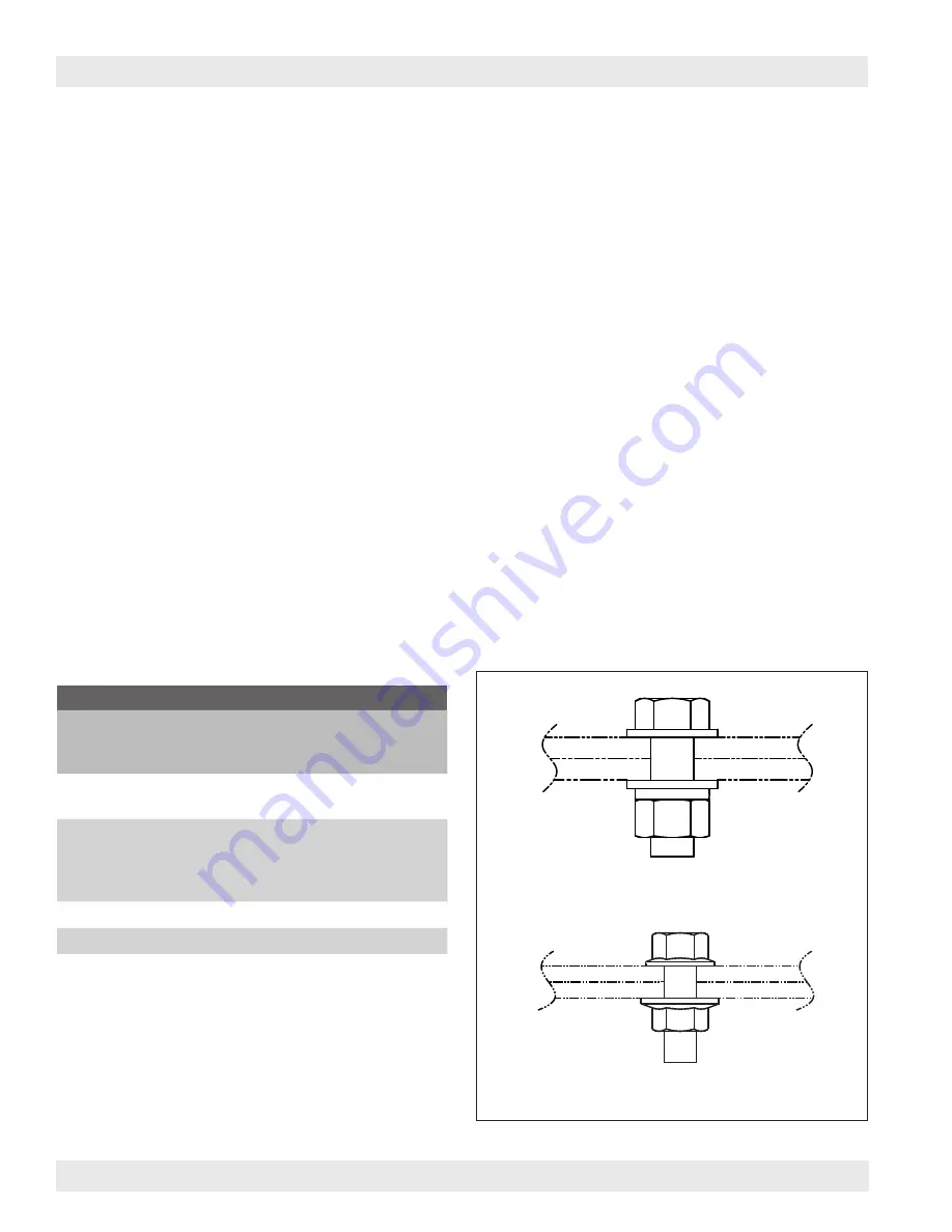
Install all tubesheet pie sections using flanged hardware in all square holes and using bolt/nut hardware in all circular holes.
Reference Hardware Table and Tubesheet Connection Layout illustration.
6.
After all pie sections are in place, bolt the center plate in place.
7. Install the center cap weldment with the center pipe inserted down through the cap plate center hole.
8. Align and tighten all bolts.
2. Tubesheet Assembly
Hardware Table
Size Assembly
Type
Recommended
Bolt Torque
(ft/lbs)
3/8-in Ladder
Platform
Bolt/Nut
Bolt/Nut
25-30
1/2-in Hopper
Body(ies)
Tangential Inlet
Roof
Flanged
Flanged
Flanged
Flanged
55-75
5/8-in Tubesheet
Bolt/Nut
110-150
3/4-in Leg Structure
Bolt/Nut
200-260
Bolt/Nut Hardware
Flanged Hardware
Hardware
Bolted connections have been designed as “non-pretensioned bolted joints” or “bearing type” connections, per AISC. Bearing type
connections require all plies of the connected elements be brought into snug tight condition. Snug tight condition is defined as the
tightness that exists when all plies in a joint are in firm contact. This may be attained by a few impacts of an impact wrench or the
full effort of an ironworker using an ordinary spud wrench to bring the plies into firm contact.
If preferred, a reference guide indicating torque values is located in the Hardware Table. Note this is a reference guide only
relaying guidance taken from hardware supplier torque-tension reference guide.


