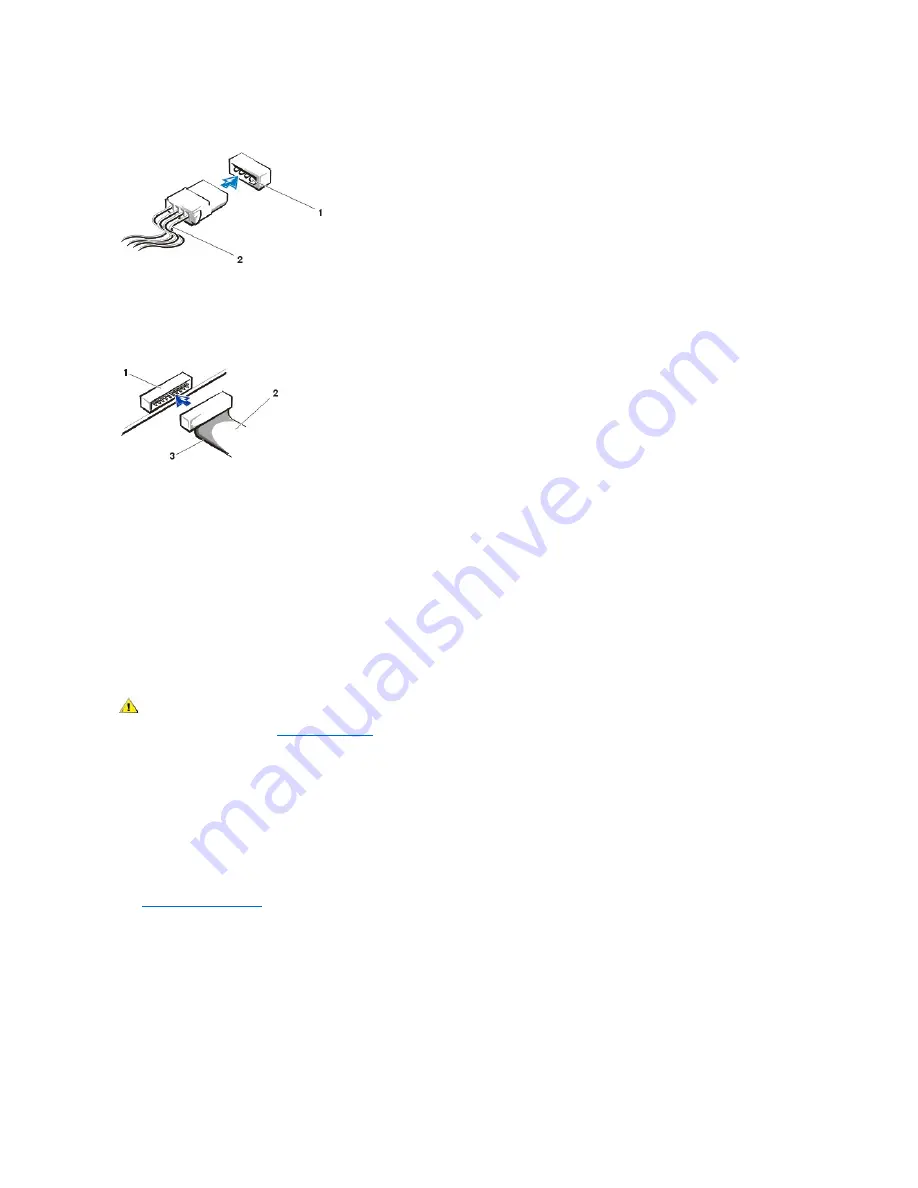
Power Cable Connector
The drive
’
s interface connector is a card-edge connector or a header connector, as shown in the following figure.
Drive Interface Connectors
When you attach the interface cable to a drive, be sure to match the colored strip on the cable to pin 1 of the drive
’
s interface connector. For the
location of pin 1 on the drive
’
s interface connector, see the documentation that came with the drive.
When you disconnect an interface cable from the system board, be sure to press in on the locking tabs on the cable connector before you
disconnect the cable. When you attach an interface cable to the system board, be sure that the locking tabs snap into place so that the cable is
firmly attached to the connector on the system board.
Most interface connectors are keyed for correct insertion; that is, a notch or a missing pin on one connector matches a tab or a filled-in hole on the
other connector. Keyed connectors ensure that the pin-1 wire in the cable (indicated by the colored strip along one edge of the cable) goes to the
pin-1 end of the connector. The pin-1 end of a connector on a board or a card is usually indicated by a silk-screened "1" printed directly on the
board or card.
NOTICE: When you connect an interface cable, do not reverse the interface cable (do not place the colored strip away from pin 1 of
the connector). Reversing the cable prevents the drive from operating and could damage the controller, the drive, or both.
Removing and Replacing Hard Drives
1. If you are replacing a hard drive that contains data you want to keep, be sure to make a backup of your files before you begin this procedure.
NOTICE: Ground yourself by touching an unpainted metal surface on the back of the chassis.
NOTICE: When you unpack the drive, do not set it on a hard surface, which may damage the drive. Instead, set the drive on a
surface, such as a foam pad, that will sufficiently cushion it.
2. Unpack the drive, and prepare it for installation.
Check the documentation for the drive to verify that it is configured for your system.
3.
Open the computer cover
.
4. On the small desktop system, remove the plastic shroud covering the hard drive by pressing in on the indented tab at the top of the shroud
and lifting the shroud away.
Removing the Hard-Drive Shroud
—
Small Desktop System
1
Power input connector
2
Power cable
1
Header connector
2
Interface cable
3
Colored strip on the cable
CAUTION: To avoid the possibility of electric shock, turn off the computer and any peripherals, disconnect them from
electrical outlets, and then wait at least 5 seconds before you open the computer cover. Also, before you install a drive, see
the other precautions in "
Safety Information
."
Содержание OptiPlex GX150
Страница 2: ...February 2002 08WUP A06 ...
Страница 97: ...Back to Contents Page ...


