background image

 
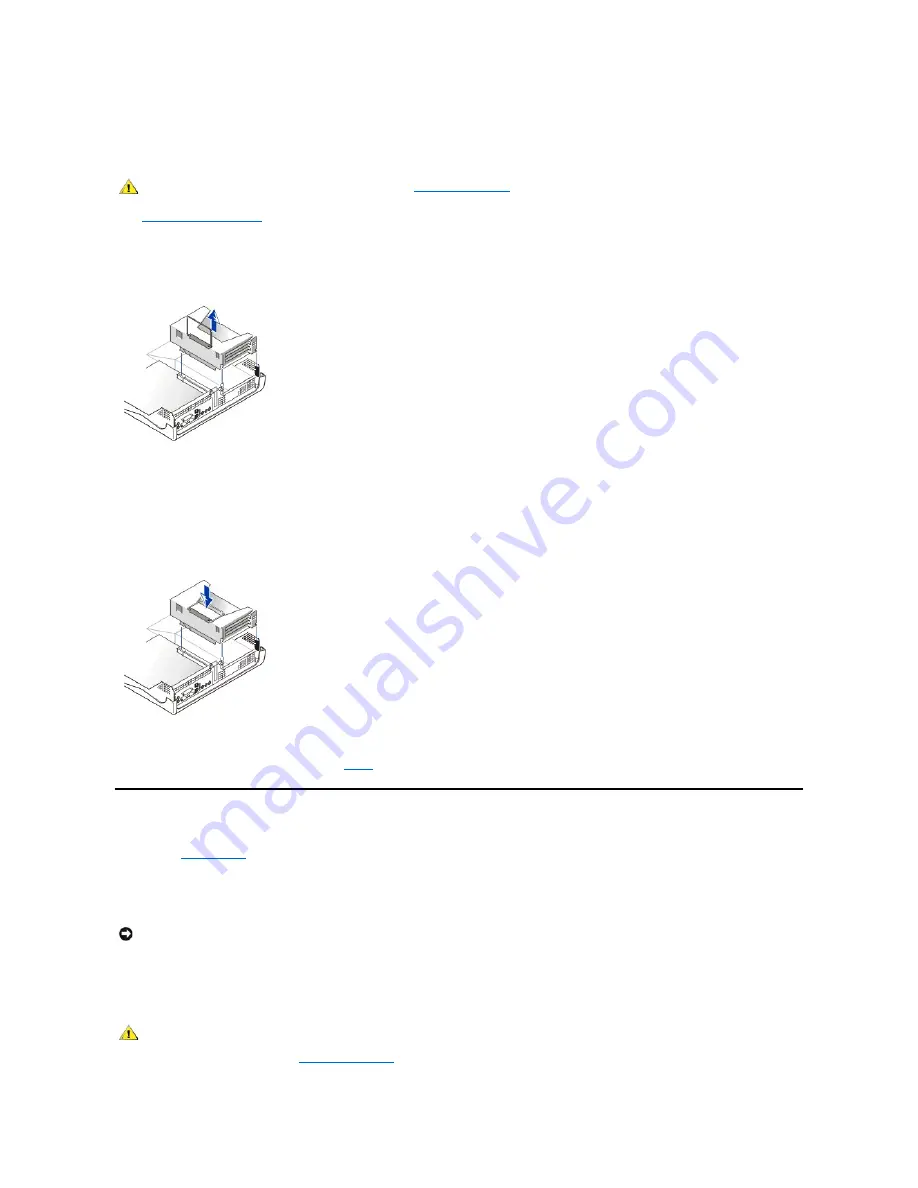
Removing and Replacing the Expansion-Card Cage in the Small Desktop System 

To remove the expansion-card cage from the small desktop system, perform the following steps. 

1.

Open the computer cover

2. Check any cables connected to expansion cards through the back-panel openings. Disconnect any cables that will not reach the cage once it 

is removed from the chassis. 

Removing the Expansion-Card Cage From the Small Desktop System


3.

Gently pull on the handle and lift  the expansion

-card cage away from the chassis.  

To replace the expansion-card cage in the small desktop system, perform the following steps: 

1. Align the slots in the side of the expansion-card cage with the tabs on the side of the system, and slide the expansion-card cage down into 

place.  

Replacing the Expansion-Card Cage In the Small Desktop System


2. Make sure that the riser board is fully seated in the connector on the system board. 


3. Reconnect any cables that you removed in 

step 2

 of the previous procedure. 

System Memory 

You can increase system memory up to 512 MB by using synchronous dynamic random-access memory (SDRAM) dual in-line memory modules 
(DIMMs). The 

system board

 illustration shows the location of the DIMM sockets on the system board (DIMMs must be non-error checking and 

correction [non-ECC]). 

When you add system memory, you may install DIMMs in either socket. For optimum operation, Dell recommends that you install a DIMM in socket 
A first (closest to the processor) before installing a DIMM in socket B. 

Installing DIMMs 

To upgrade memory, perform the following steps. 

CAUTION: Before you perform this procedure, see "

Safety Information

."

NOTICE: Before you install new memory modules, download the most recent BIOS for your computer from the Dell Support website at 

support.dell.com

CAUTION: To avoid the possibility of electric shock, turn off the computer and any peripherals, disconnect them from their 
electrical outlets, and then wait at least 5 seconds before you open the computer cover. Also, before you upgrade memory, 
see the other precautions in "

Safety Information

. "

Содержание OptiPlex GX150

Страница 1: ...Dell disclaims any proprietary interest in trademarks and trade names other than its own Reader Survey We want to hear from you Please take our document survey Safety Information Overview When Using Your Computer Ergonomic Computing Habits When Working With Your Computer Electrostatic Discharge About Your Computer Front View Back View Inside Your Computer Advanced Features Manageability Security P...

Страница 2: ...February 2002 08WUP A06 ...

Страница 3: ...one connector This door is removable if you remove it or accidentally knock it off its hinges it snaps back in place View With the Front Panel Door Open on the Small Desktop System Front View Back View Inside Your Computer 1 USB connectors 2 2 Headphone connector 3 Hard drive access indicator 4 Power button 5 Power indicator 1 Front panel door 2 Power button 3 Power indicator 4 Removable optical d...

Страница 4: ...ndows 98 SE Windows 2000 and Windows XP With Dell AutoShutdown Loaded Pressing or holding the power button to shut down the system may result in data loss Use the power button to shut down the system only if the operating system is not responding The following table shows power button functions for Microsoft Windows NT operating systems 1 USB connectors 2 do not use these front connectors for USB ...

Страница 5: ...l this indicator turns off before you remove the diskette from the drive Hard Drive Access Indicator The hard drive access indicator lights when the system is reading data from or writing data to the drive Back View The following figure shows the connectors and indicators on the back of your computer for attaching external devices Small Form Factor System Back Panel Connectors and Indicators I O P...

Страница 6: ...vity indicator see Integrated NIC connector 7 Video connector 8 PCI slots 9 AC voltage switch 10 AC power connector 11 Half height AGP slot 12 Line out jack line in jack and microphone jack 13 USB connectors 14 Keyboard connector 15 Serial port 2 connector 16 Serial port 1 connector 1 AC power connector 2 AC voltage switch 3 Parallel port connector 4 Mouse connector 5 Link integrity indicator see ...

Страница 7: ...yellow activity indicator flashes when the system is transmitting or receiving network data A high volume of network traffic may make this indicator appear to be in a steady on state l A dual colored link integrity indicator which is green when there is a good connection between a 10 megabit per second Mbps network and the NIC and orange when there is a good connection between a 100 Mbps network a...

Страница 8: ...ures show the desktop systems with their covers opened Inside the Small Form Factor Chassis Inside the Small Desktop Chassis Inside the Small Mini Tower Chassis NOTE Do not use this connector if your computer contains an add in accelerated graphics port AGP and or Peripheral Component Interconnect PCI card This connector can be used for a secondary display if multi monitor is supported and enabled...

Страница 9: ...assis intrusion switch 6 System board 7 Expansion card slots 8 I O ports and connectors 9 AC power connector 10 Power supply 11 Padlock ring 12 Microprocessor and heat sink shroud 1 CD drive data cable 2 Floppy drive data cable 3 Control panel cable 4 CD drive power cable 5 IDE drive power cable hard drive 6 IDE data cable hard drive 7 Input output cable 8 Input output audio cable 9 CD audio cable...

Страница 10: ...l drive cable 3 Diskette drive cable 4 Control panel cable 5 Front input output cable 6 Front input output audio cable 7 EIDE interface cable hard drive 1 Optical drive audio cable 2 Optical drive cable 3 Diskette drive cable 4 Control panel cable 5 Front input output cable 6 Front input output audio cable 7 EIDE interface cable hard drive ...

Страница 11: ...of Computer 1 PC speaker 2 DC power connector 3 Diskette drive connector 4 Battery 5 EIDE2 connector 6 Auxiliary power indicator 7 Memory module DIMM connectors 2 8 Front panel cable connector 9 EIDE1 connector 10 PCI 2 riser connector not populated on the small form factor chassis used as the riser in the small desktop chassis and can be populated with PCI expansion card in the small mini tower c...

Страница 12: ...ery socket CD IN CD ROM drive audio cable connector DIAG_LED Diagnostic LEDs DIMM_x Dual in line memory module DIMM socket DSKT Diskette drive interface connector FAN Microprocessor fan connector FRONTAUDIO Front panel audio connector for onboard audio FRONTPANEL Front panel cable connector IDEn EIDE interface connector KYBD_MOUSE Keyboard and mouse connectors MICROPROCESSOR Microprocessor connect...

Страница 13: ...should match the electromagnetic environment classification of the computer system A Notice About Shielded Signal Cables Use only shielded cables for connecting peripherals to any Dell device to reduce the possibility of interference with radio communications services Using shielded cables ensures that you maintain the appropriate EMC classification for the intended environment For parallel printe...

Страница 14: ...istration labels located on the bottom or the back panel of your computer or other digital apparatus A statement in the form of IC Class A ICES 003 or IC Class B ICES 003 will be located on one of these labels Note that Industry Canada regulations provide that changes or modifications not expressly approved by Dell could void your authority to operate this equipment CE Notice European Union Markin...

Страница 15: ...y Control Council for Interference VCCI as Class B information technology equipment ITE However the inclusion of certain options can change the rating of some configurations to Class A ITE including peripherals expansion cards printers input output I O devices monitors and so on integrated into or connected to the system should match the electromagnetic environment classification Class A or B of t...

Страница 16: ... suitable for your use you may exchange it for a nonbusiness purpose device MIC Class A Regulatory Label Class B Device Please note that this device has been approved for nonbusiness purposes and may be used in any environment including residential areas MIC Class B Regulatory Label Polish Center for Testing and Certification Notice The equipment should draw power from a socket with an attached pr...

Страница 17: ...formación siguiente se proporciona en el dispositivo o en los dispositivos descritos en este documento en cumplimiento con los requisitos de la Norma Oficial Mexicana NOM Exporter Dell One Dell Way Round Rock TX 78682 Importer Dell Computer de México S A de C V Paseo de la Reforma 2620 11 Piso Col Lomas Altas 11950 México D F Ship to Dell Computer de México S A de C V al Cuidado de Kuehne Nagel de...

Страница 18: ...e la Reforma 2620 11 Piso Col Lomas Altas 11950 México D F Embarcar a Dell Computer de México S A de C V al Cuidado de Kuehne Nagel de México S de R I Avenida Soles No 55 Col Peñon de los Baños 15520 México D F Tensión alimentación 115 230 VAC Frecuencia 60 50 Hz Consumo de corriente DHS 2 0 1 0 A DHP 1 5 0 75 A DHM 3 0 1 5 A ...

Страница 19: ... power management features of the computer are enabled ENERGY STAR Emblem NOTES As an ENERGY STAR Partner Dell has determined that this product meets the ENERGY STAR guidelines for energy efficiency Any Dell computer bearing the ENERGY STAR Emblem is certified to comply with EPA ENERGY STAR requirements as configured when shipped by Dell Any changes you make to this configuration such as installin...

Страница 20: ...are returned to Dell s facility To request warranty service you must call Dell s Customer Technical Support within the warranty period See Getting Help to obtain customer assistance If warranty service is required Dell will issue a Return Material Authorization Number You must ship the products back to Dell in their original or equivalent packaging prepay shipping charges and insure the shipment o...

Страница 21: ... program are not covered Batteries for portable computers are covered only during the initial one year period of this limited warranty Coverage During Year One During the one year period beginning on the invoice date Dell will repair or replace products covered under this limited warranty that are returned to Dell s facility To request warranty service you must call Dell s Customer Technical Suppo...

Страница 22: ...w and reconditioned parts made by various manufacturers in performing repairs and building replacement products Exclusions This Guarantee does not apply to defects resulting from improper or inadequate installation use or maintenance actions or modifications by unauthorized third parties or the end user accidental or willful damage or normal wear and tear Making a Claim Claims must be made in Lati...

Страница 23: ...ing Help to obtain customer assistance To expedite the processing of your refund or credit Dell expects you to return the products to Dell in their original packaging within five days of the date that Dell issues the Credit Return Authorization Number You must also prepay shipping charges and insure the shipment or accept the risk of loss or damage during shipment You may return software for refun...

Страница 24: ... every day week or month at a certain hour on the hour or they can enable inventory as needed Support for the application program used to create user definable attributes UDAs Asset management features Remote viewing entering and modifying of an asset tag for a remote system in a Dell DMI network Automated and manual mapping of one or more groups to a user defined directory For more information ab...

Страница 25: ...access the System Security option s pop up menu 4 Press the down arrow keys to move to the Chassis Intrusion option 5 Press the spacebar to select an option setting Option settings l Enabled When the computer cover is opened with this setting a DMI event is generated the setting changes to Detected and the following message appears during the boot routine at the next system start up Alert Cover wa...

Страница 26: ...racters As you press each character key or the spacebar for a blank space a placeholder appears in the field The password assignment operation recognizes keys by their location on the keyboard without distinguishing between lowercase and uppercase characters For example if you have an M in your password the system recognizes either M or m as correct Certain key combinations are not valid If you en...

Страница 27: ...or the System Password option If Not Enabled appears in the System Password option the system password has been deleted If you want to assign a new password continue to step 6 If Not Enabled is not displayed for the System Password option press Alt B to reboot the system and then repeat steps 3 through 5 6 To assign a new password follow the procedure in Assigning a System Password Setup Password ...

Страница 28: ...erals to an electrical outlet and then turn them on This erases the existing password s 5 Enter the system setup program and verify that the password is disabled Proceed to step 6 if you want to assign a new password 6 Open the computer cover 7 Replace the PSWD jumper plug 8 Close the computer cover and reconnect the computer and peripherals to an electrical outlet and turn them on Booting your sy...

Страница 29: ...organized into four areas l Title the box at the top of all screens lists the computer system name l Computer data two boxes below the title box that display your system processor level 2 L2 cache service tag and the version number of the basic input output system BIOS l Options a scrollable box listing options that define the configuration of your computer including installed hardware power conse...

Страница 30: ...rom the next device in the boot sequence list Additional System Setup Options l AC Power Recovery determines what happens when AC power is restored to the system When Off is selected the system remains off when AC power is restored When On is selected the system starts up when AC power is restored When Last is selected the system returns to the AC power state existing at the time that AC power was...

Страница 31: ...llowing subsections Sound determines whether the integrated audio controller is On or Off The default is On Network Interface Controller determines whether the integrated NIC is On Off or On w MBA The default is On If you select On w MBA you are prompted to press Ctrl Alt b at the Dell logo screen during system boot A menu then appears that allows you to select PXE RPL BootP or NetWare as the acti...

Страница 32: ...em uses a video expansion card if one is installed or the onboard video controller if a video expansion card is not installed When Onboard is selected the system uses the onboard video controller even if a video expansion card is installed Video DAC Snoop lets you correct video problems that may occur when you use certain video expansion cards The default is Off If you are using a video expansion ...

Страница 33: ...1 and User 2 settings only two user defined drive types are allowed Then press the Tab key to highlight each of the parameter fields in succession and enter the appropriate number for each field l Remote Wake Up allows you to set the Remote Wake Up feature to On or Off You must reboot your system before a change takes effect l Report Keyboard Errors enables or disables reporting of keyboard errors...

Страница 34: ...Installation and Configuration When you obtain software check it for viruses with virus scanning software before installing it on your computer s hard drive Viruses which are pieces of code that can replicate themselves can quickly use all available system memory damage or destroy data stored on the hard drive and permanently affect the performance of the programs they infect Several commercial vi...

Страница 35: ...d city codes For example to call Paris France from Montpellier France dial the area code plus the local number as shown in the following illustration The codes required depend on where you are calling from as well as the destination of your call in addition each country has a different dialing protocol If you need assistance in determining which codes to use contact a local or an international ope...

Страница 36: ...27 11 Spain Madrid 00 34 91 Sweden Upplands Vasby 00 46 8 Switzerland Geneva 00 41 22 Taiwan 002 886 Thailand 001 66 U K Bracknell 010 44 1344 U S A Austin Texas 011 1 Not required Country City Department Name or Service Area Code Local Number or Toll Free Number Antigua and Barbuda General Support 1 800 805 5924 Argentina Buenos Aires Technical Support Customer Care toll free 0800 444 0733 Sales ...

Страница 37: ...9 Cayman Islands General Support 1 800 805 7541 Chile Santiago NOTE Customers in Chile call the U S A for sales customer and technical assistance Sales Customer Support and Technical Support toll free 1230 020 4823 Colombia General Support 980 9 15 3978 Costa Rica General Support 800 012 0435 Dominican Republic General Support 1 800 148 0530 El Salvador General Support 01 889 753 0777 Guatemala Ge...

Страница 38: ...stem toll free 1 800 433 9014 AutoTech For portable and desktop computers toll free 1 800 247 9362 Dell Home and Small Business Group For portable and desktop computers Customer Technical Support Return Material Authorization Numbers toll free 1 800 624 9896 Customer Technical Support Home sales purchased via www dell com toll free 1 877 576 3355 Customer Service Credit Return Authorization Number...

Страница 39: ... Support 8001 3605 Country City Department Name or Service Area Code Local Number or Toll Free Number Austria Vienna NOTE Customers in Austria call Langen Germany for Technical Support and Customer Care Switchboard 01 491 040 Home Small Business Sales 01 795676 02 Home Small Business Sales Fax 01 795676 05 Home Small Business Customer Care 01 795676 03 Preferred Accounts Corporate Customer Care 06...

Страница 40: ...ic_server_support dell com Finland Helsinki Technical Support 09 253 313 60 Technical Support Fax 09 253 313 81 Relational Customer Care 09 253 313 38 Home Small Business Customer Care 09 693 791 94 Fax 09 253 313 99 Switchboard 09 253 313 00 Website support euro dell com E mail fin_support dell com France Paris Montpellier Home and Small Business Technical Support 0825 387 270 Customer Care 0825 ...

Страница 41: ... 907 4000 SalesFax 01 204 0144 Ireland Fax 01 204 5960 Switchboard 01 204 4444 Website support euro dell com E mail dell_direct_support dell com Italy Milan Home and Small Business Technical Support 02 577 826 90 Customer Care 02 696 821 14 Fax 02 696 821 13 Switchboard 02 696 821 11 Website support euro dell com E mail support euro dell com it it emaildell Corporate Technical Support 02 577 826 9...

Страница 42: ...r Care 231 62298 Switchboard 671 16800 Fax Technical Support Upplands Vasby Sweden 00 46 08 590 05 594 Fax Switchboard 671 16865 Website support euro dell com E mail nor_support dell com E mail Support for Servers Nordic_server_support dell com Poland Warsaw Customer Service Phone 22 57 95 700 Customer Care 22 57 95 999 Sales 22 57 95 999 Switchboard 22 57 95 999 Customer Service Fax 22 57 95 806 ...

Страница 43: ...eneva Technical Support Home and Small Business 0844 811 411 Technical Support Corporate 0844 822 844 Customer Care Home and Small Business 0848 802 202 Customer Service Corporate 0848 821 721 Switchboard 022 799 01 01 Fax 022 799 01 90 Website support euro dell com E mail for French Speaking HSB and Corporate Customers support euro dell com ch fr emaildell U K Bracknell Technical Support Corporat...

Страница 44: ... 2999 Large Corporate Accounts East toll free 800 858 2020 Large Corporate Accounts South toll free 800 858 2355 Large Corporate Accounts GCP toll free 800 858 2055 Large Corporate Accounts HK toll free 800 964108 Large Corporate Accounts GCP HK toll free 800 907308 Hong Kong NOTE Customers in Hong Kong call Malaysia for customer assistance Technical Support toll free 800 96 4107 Customer Service ...

Страница 45: ...1 800 888 213 New Zealand Home and Small Business 0800 446 255 Government and Business 0800 444 617 Sales 0800 441 567 Fax 0800 441 566 Singapore Singapore NOTE Customers in Singapore call Malaysia for customer assistance Technical Support toll free 800 6011 051 Customer Service Penang Malaysia 04 633 4949 Transaction Sales toll free 800 6011 054 Corporate Sales toll free 800 6011 053 South Africa...

Страница 46: ...33 556 Corporate Sales toll free 0080 651 227 0800 33 555 Thailand NOTE Customers in Thailand call Malaysia for customer assistance Technical Support toll free 088 006 007 Customer Service Penang Malaysia 633 4949 Sales toll free 088 006 009 ...

Страница 47: ...e attached to the middle connector on the interface cable is the slave device drive 1 With the two EIDE interface connectors on the system board your system supports up to two EIDE devices EIDE hard drives should be connected to the EIDE interface connector labeled IDE1 Always connect EIDE tape drives and CD ROM drives to the EIDE interface connector labeled IDE2 Connecting Drives When you install...

Страница 48: ...rface which may damage the drive Instead set the drive on a surface such as a foam pad that will sufficiently cushion it 2 Unpack the drive and prepare it for installation Check the documentation for the drive to verify that it is configured for your computer system 3 Open the computer cover 4 Remove the drive bracket from the chassis a Disconnect the power and interface cables from the drive b Pr...

Страница 49: ...reboot the system 15 Partition and logically format your drive before you proceed to the next step See the documentation for your operating system for instructions 16 Test the hard drive by running the Dell Diagnostics Small Desktop System Hard Drives To install an EIDE hard drive in a small desktop system perform the following steps 1 If you are replacing a hard drive that contains data you want ...

Страница 50: ...tached remove the four screws holding the hard drive to the bracket rails Removing the Hard Drive in the Small Desktop System 7 Attach the bracket rails to the new hard drive by aligning the four screw holes of the drive and bracket and then inserting and tightening the screws that came with your upgrade kit 8 Reinstall the hard drive bracket in the chassis by gently sliding the bracket into place...

Страница 51: ... install an EIDE hard drive in a small mini tower system perform the following steps 1 If you are replacing a hard drive that contains data you want to keep be sure to make a backup of your files before you begin this procedure NOTICE Ground yourself by touching an unpainted metal surface on the back of the computer NOTICE When you unpack the drive do not set it on a hard surface which may damage ...

Страница 52: ...of the drive and connect one of the device connectors on the EIDE cable to the 40 pin interface connector on the back of the hard drive Check all connectors to be certain that they are properly cabled and firmly seated Attaching Hard Drive Cables in the Small Mini Tower System 11 If it is not already connected connect the other end of the EIDE cable to the IDE1 connector on the system board 12 Clo...

Страница 53: ... Disconnect the power cable and the floppy drive cable from the back of the drive On the small form factor desktop system also remove the other end of the floppy cable from the connector on the system board 2 Press inward on the two tabs on the sides of the drive bay to disengage the bracket from the chassis 3 Slide the bracket upward and remove it from the chassis Removing the 3 5 Inch Floppy Dri...

Страница 54: ...on the two tabs on the sides of the drive bay to disengage the bracket from the chassis b Slide the bracket upward and remove it from the chassis Removing the 5 25 Inch Drive in the Small Form Factor Desktop System 2 If the replacement drive does not have the bracket rails attached remove the old drive from the bracket by removing the four screws that secure the drive to the bracket rails 3 Attach...

Страница 55: ...t the cable from the drive to the interface connector labeled DSKT on the system board l For a drive that comes with its own controller card connect the other end of the interface cable to the controller card 9 Check all cable connections and fold cables out of the way to provide airflow for the fan and cooling vents 10 If the 5 25 inch drive bay was previously empty remove the front panel insert ...

Страница 56: ...acket assembly To remove and install the 3 5 inch floppy drive and bracket assembly perform the following steps 1 Press inward on the two tabs on the sides of the drive bay to disengage the bracket from the chassis 2 Slide the bracket upward and remove it from the chassis Removing the 3 5 Inch Floppy Drive in the Small Desktop System 3 If the replacement drive does not have the bracket rails attac...

Страница 57: ...ngage the bracket from the chassis b Slide the bracket upward and remove it from the chassis Removing the 5 25 Inch Drive in the Small Desktop System 2 If the replacement drive does not have the bracket rails attached remove the old drive from the bracket by removing the four screws that secure the drive to the bracket rails 3 Attach the bracket to the new drive by aligning the screw holes on the ...

Страница 58: ...board l For a drive that comes with its own controller card connect the other end of the interface cable to the controller card 10 Check all cable connections and fold cables out of the way to provide airflow for the fan and cooling vents 11 If the 5 25 inch drive bay was previously empty remove the front panel insert from the front panel a Remove the 5 25 inch front panel with your fingers or car...

Страница 59: ... to step 5 1 Press inward on the two tabs on the sides of the drive bay to disengage the bracket from the chassis 2 Slide the bracket upward and remove it from the chassis Removing the 3 5 Inch Floppy Drive in the Small Mini Tower System 3 If the replacement drive does not have the bracket rails attached remove the old drive from the rails by removing the four screws that secure them to the drive ...

Страница 60: ...Attaching Floppy Drive Cables in the Small Mini Tower System To remove and install a 5 25 inch drive in a small mini tower system perform the following steps 1 If you are replacing a 5 25 inch drive and bracket assembly follow these instructions If you are installing a new drive skip to step 4 a Press inward on the two tabs on the sides of the drive bay to disengage the bracket from the chassis b ...

Страница 61: ... remove the insert by pressing on the four tabs and pulling the insert away from the panel Replace the front panel by snapping into place 6 Install the 5 25 inch floppy drive and bracket assembly in the chassis by gently sliding the bracket into place until the tabs securely click into position 7 If you are installing a drive that has its own controller card install the controller card in an expan...

Страница 62: ...nter system setup and update the appropriate Diskette Drive A or Diskette Drive B option to reflect the size and capacity of your new floppy drive l If you installed a non EIDE tape drive as the second drive set the Diskette Drive B option to Not Installed l If you installed an EIDE CD ROM or tape drive set the appropriate Drive option 0 or 1 under Drives Secondary to Auto See Primary Drive n and ...

Страница 63: ... is your most powerful tool for obtaining information about your computer and other Dell products Through the Internet you can access most of the services described in this section including AutoTech TechFax order status technical support and product information You can access Dell Support at support dell com Select your region on the WELCOME TO DELL SUPPORT page and fill in the requested details ...

Страница 64: ...ustry leading hardware technical support service is available 24 hours a day seven days a week to answer your questions about Dell hardware Our technical support staff pride themselves on their track record more than 90 percent of all problems and questions are taken care of in just one toll free call usually in less than 10 minutes When you call our experts can see records kept on your Dell syste...

Страница 65: ... possible only at the computer system itself Make sure the system documentation is available Diagnostics Checklist Back to Contents Page NOTE Have your Express Service Code ready when you call The code helps Dell s automated support telephone system direct your call more efficiently CAUTION If you need to remove the computer covers be sure to first disconnect the computer system s power and modem ...

Страница 66: ...em User s Guide Getting Help Dell OptiPlex GX150 System User s Guide Contents Dell OptiPlex GX150 System User s Guide Solving Problems Dell OptiPlex GX150 System User s Guide Safety Information Dell OptiPlex GX150 System User s Guide Technical Specifications Dell OptiPlex GX150 System User s Guide Stand Dell OptiPlex GX150 System User s Guide Installing Upgrades Dell OptiPlex GX150 System User s G...

Страница 67: ...urge protector remove it 3 Make sure the power cable is firmly connected to the computer and then verify that the power cable is directly connected to the electrical Finding Solutions Software Problems Dell Diagnostics BIOS Recovery Utility Messages and Codes Power indicator does not light See Power Problems Monitor power indicator does not light See Video and Monitor Problems No sound See Sound a...

Страница 68: ...s fill out the Diagnostics Checklist as you perform the following steps 1 Turn off the computer wait at least 30 seconds and then turn the computer back on 2 Allow 1 minute for the computer to initialize its components and then adjust the monitor s brightness and contrast controls Is the monitor readable Yes The problem is resolved No Go to step 3 3 Turn off nearby fans lights lamps or other elect...

Страница 69: ...or other electrical devices Are the external speakers functioning properly Yes One or more of those electrical devices was causing interference The problem is resolved No Go to step 2 2 Enter system setup and make sure that Sound under the Integrated Devices option is set to On Then exit system setup properly to save the information and reboot the system Is the device working properly Yes The prob...

Страница 70: ...Basic Checks l Disconnect the cable from the computer and check the cable connector for bent or broken pins Check for damaged or frayed cables l If the cable is not damaged make sure that it is firmly connected to the computer l Test the electrical outlet Verify that the device is connected to a working electrical outlet l Verify that the device is turned on l Check for interference electrical app...

Страница 71: ...l for technical assistance Mouse Problems Basic Checks l Disconnect the cable from the computer and check the cable connector for bent or broken pins Check for damaged or frayed cables l If the cable is not damaged make sure that it is firmly connected to the computer l Reinstall the mouse driver for your operating system l Restart the computer If the problem still exists after you complete the ba...

Страница 72: ...e usually on the bottom of the keyboard sometimes behind a panel Refer to the documentation that came with the keyboard for more information 5 Turn off the computer wait 30 seconds and turn it on again During the boot routine do the Num Lock Caps Lock and Scroll Lock lights on the keyboard blink momentarily Yes Go to step 6 No Go to step 7 6 Use the keyboard to type some characters Do the characte...

Страница 73: ...the Dell Diagnostics Did any of the tests fail Yes Contact Dell for technical assistance No Go to step 2 2 Turn off the computer and peripherals disconnect them from their electrical outlets wait at least 5 seconds and then open the computer cover 3 Remove and reinstall the diskette drive 4 Close the computer cover reconnect the computer and peripherals to their electrical outlets and turn them on...

Страница 74: ...tes and displays a status report and lists and corrects errors on the disk l For Windows NT run the error checking utility by double clicking My Computer and selecting the hard drive that you want to check Click the right mouse button select Properties then click Tools and select Check Now in the Error Checking section l For Windows 98 SE and Windows 98 run the ScanDisk utility by clicking the Sta...

Страница 75: ...lved No Contact Dell for technical assistance Battery Problems If an error message indicates a problem with the battery or if configuration information is lost from system setup when the computer is turned off the battery may be defective 1 Turn off the computer and peripherals disconnect them from their electrical outlets wait at least 5 seconds and then open the computer cover 2 Reseat the batte...

Страница 76: ... The problem is resolved No You may have a faulty expansion card Proceed to step 7 7 Turn off the computer and peripherals disconnect them from their electrical outlets wait at least 5 seconds and then open the computer cover 8 Remove all expansion cards except the video card 9 Close the computer cover reconnect the computer and peripherals to their electrical outlets and turn them on 10 Run the R...

Страница 77: ...east 5 seconds and then open the computer cover 7 Reinstall all expansion cards 8 If you have a micro tower chassis replace the AGP card brace 9 Close the computer cover reconnect the computer and peripherals to their electrical outlets and turn them on 10 Run the System Board Devices test group in the Dell Diagnostics Did any of the diagnostics tests fail Yes Contact Dell for technical assistance...

Страница 78: ...e computer s memory determines the amount of installed memory and then writes to and reads from the number of available bytes to ensure proper operation Basic Checks l If an insufficient memory message appears save and close any open files and exit any open application programs not in use l Consider installing additional system memory l Run the System Memory test in the Dell Diagnostics l Reseat t...

Страница 79: ...computer cover 3 Make sure the power cables from the power supply are firmly connected to the connectors on the system board 4 Close the computer cover reconnect the computer and peripherals to their electrical outlets and turn them on Is the computer working properly Yes The problem is resolved No Go to step 5 5 Perform the procedure in Expansion Card Problems Is the computer working properly Yes...

Страница 80: ...checks or extensive tests on one or all devices l Choose the number of times a test group or subtest is repeated l Display or print test results or save them in a file l Suspend testing if an error is detected or terminate testing when an adjustable error limit is reached l Access online Help screens that describe the tests and tell how to run them l Read status messages that inform you whether te...

Страница 81: ...to MS DOS Exits to the MS DOS prompt 10 Select the type of tests to perform l To perform a quick check of your computer or a specific device select Quick Tests from the Test All Devices or Test One Device option Quick Tests runs only the tests that run fast and do not require user interaction Dell recommends that you choose Quick Tests first to increase the odds of tracing the source of the proble...

Страница 82: ...elow for suggestions on resolving any problems indicated by the message The system messages are listed alphabetically NOTE The groups and devices listed in your screen can vary somewhat based on the components installed in your computer NOTE The diagnostics may not list in the Device Groups area the names of all components or devices that are part of your computer system For example it may not lis...

Страница 83: ...read the data Run the chkdsk utility in the Microsoft Windows operating system to check the file structure of the diskette or hard drive See your operating system documentation for more information If you are using another operating system run the appropriate utility to check the file structure of the diskette or hard drive See your operating system documentation Decreasing available memory One or...

Страница 84: ...emory test No boot device available The computer cannot find the diskette or hard drive Enter system setup check the system configuration information for the diskette and hard drive and if necessary correct the information No boot sector on hard disk drive The system configuration information in system setup may be incorrect or the operating system may be corrupted Enter system setup check the sys...

Страница 85: ...l Diagnostics Unexpected interrupt in protected mode The keyboard controller may be malfunctioning or one or more DIMMs may be loose Run the System Memory and the Keyboard tests in the Dell Diagnostics WARNING Dell s Disk Monitoring System has detected that drive 0 1 on the primary secondary EIDE controller is operating outside of normal specifications It is advisable to immediately back up your d...

Страница 86: ...elp for instructions on obtaining technical assistance 3 3 1 NVRAM power loss Run the System Board Devices tests in the Dell Diagnostics if possible 3 3 2 NVRAM configuration Run the System Board Devices tests in the Dell Diagnostics if possible 3 3 4 Video Memory Test failure Run the VESA VGA Interface tests in the Dell Diagnostics 3 4 1 Screen initialization failure Run the VESA VGA Interface te...

Страница 87: ...e Getting Help for instructions on obtaining technical assistance Solid green and a beep code during POST A problem was detected while the BIOS was executing See Table 2 for instructions on diagnosing the beep code Solid green power indicator with no beep code and no video during POST The monitor or the graphics card may be faulty See Video and Monitor Problems If the monitor is operating properly...

Страница 88: ...possibility of a program conflict by rebooting your computer system l Make sure that a hardware conflict does not exist between devices Operating System Compatibility Make sure the computer s operating environment is set up to accommodate the application programs you use Whenever you change the operating environment parameters you may also affect the successful operation of the application program...

Страница 89: ...s conflicts occur when two or more devices try to access the same address in the upper memory blocks UMB For example if a network expansion card and an expanded memory page frame are assigned an overlapping block of addresses a memory address conflict arises As a result when you try to log in to the network the operation fails To resolve this type of conflict you can change the address of one of t...

Страница 90: ...te 3 On the working system go to an MS DOS prompt and type the command xxxxx writehdrfile where xxxxx is the name of the BIOS flash executable utility you downloaded Running this utility generates a file with an hdr extension 4 Copy the hdr file to a diskette 5 Insert the diskette into the diskette drive of the corrupted system and turn it on The system automatically flashes the BIOS from the disk...

Страница 91: ...ntial environments Information Technology Equipment ITE including peripherals expansion cards printers input output I O devices monitors and so on that are integrated into or connected to the system should match the electromagnetic environment classification of the computer system A Notice About Shielded Signal Cables Use only shielded cables for connecting peripherals to any Dell device to reduce...

Страница 92: ...nto an outlet on a circuit different from that to which the receiver is connected l Consult the dealer or an experienced radio television technician for help The following information is provided on the device or devices covered in this document in compliance with FCC regulations l Model number DHS DHP and DHM l Company name Dell Computer Corporation One Dell Way Round Rock Texas 78682 USA 512 338...

Страница 93: ... a joint effort between the EPA and computer manufacturers to reduce air pollution by promoting energy efficient computer products The EPA estimates that use of ENERGY STAR computer products can save computer users up to two billion dollars annually in electricity costs In turn this reduction in electricity usage can reduce emissions of carbon dioxide the gas primarily responsible for the greenhou...

Страница 94: ...ent is used in a domestic environment radio disturbance may arise When such trouble occurs the user may be required to take corrective actions Figure 1 VCCI Class A ITE Regulatory Mark Class B ITE This is a Class B product based on the standard of the Voluntary Control Council for Interference VCCI for information technology equipment If this equipment is used near a radio or television receiver i...

Страница 95: ...nt should draw power from a socket with an attached protection circuit a three prong socket All equipment that works together computer monitor printer and so on should have the same power supply source The phasing conductor of the room s electrical installation should have a reserve short circuit protection device in the form of a fuse with a nominal value no larger than 16 amperes A To completely...

Страница 96: ...orter Dell One Dell Way Round Rock TX 78682 Importer Dell Computer de México S A de C V Paseo de la Reforma 2620 11 Piso Col Lomas Altas 11950 México D F Ship to Dell Computer de México S A de C V al Cuidado de Kuehne Nagel de México S de R I Avenida Soles No 55 Col Peñon de los Baños 15520 México D F Supply voltage 115 230 VAC Frequency 60 50 Hz Input current rating DHS 2 0 1 0 A DHP 1 5 0 75 A D...

Страница 97: ...Back to Contents Page ...

Страница 98: ...d power sources These cables are equipped with three prong plugs to help ensure proper grounding Do not use adapter plugs or remove the grounding prong from a cable If you must use an extension cable use a three wire cable with properly grounded plugs l To help protect your computer from sudden transient increases and decreases in electrical power use a surge suppressor line conditioner or uninter...

Страница 99: ...arms hang naturally at your sides l Sit erect with your feet resting on the floor and your thighs level l When sitting make sure the weight of your legs is on your feet and not on the front of your chair seat Adjust your chair s height or use a footrest if necessary to maintain proper posture l Vary your work activities Try to organize your work so that you do not have to type for extended periods...

Страница 100: ...processor chip by its edges not by its pins Protecting Against Electrostatic Discharge Static electricity can harm delicate components inside your computer To prevent static damage discharge static electricity from your body before you touch any of your computer s electronic components such as the microprocessor You can do so by touching an unpainted metal surface on the computer chassis As you co...

Страница 101: ...ory module DIMM sockets two non error checking and correction non ECC DIMM capacities 64 128 and 256 megabyte MB SDRAM System random access memory RAM 64 to 512 MB Basic input output system BIOS address F0000h System Information System chip set Intel 815E Data bus width 64 bits Address bus width 32 bits Direct memory access DMA channels 7 Interrupts 15 System BIOS Desktop Management Interface DMI ...

Страница 102: ...e cards are supported card size 6 35 cm 2 5 inches high by 16 76 cm 6 6 inches long Small desktop SD chassis expansion card connectors two PCI expansion slots card size 10 67 cm 4 2 inches high by 17 65 cm 6 95 inches long Small mini tower SMT chassis expansion card connectors four PCI expansion slots card sizes three slots support cards up to 27 9 cm high 11 inches and one slot supports a card up...

Страница 103: ...icroprocessor speeds on 101 key keyboard in MS DOS real mode only Ctrl Alt toggles microprocessor speeds on 102 key keyboard in MS DOS real mode only F2 or Ctrl Alt Enter starts embedded system setup during power on system test POST only F3 or F12 automatically starts boots the system from the network environment specified by the managed boot agent MBA rather than from one of the devices in the sy...

Страница 104: ...35 4 cm 13 93 inches Weight 6 9 kg 15 lbs Small desktop chassis Height 10 6 cm 4 2 inches Width 38 9 cm 15 3 inches Depth 43 2 cm 17 inches Weight 9 9 kg 22 lbs Small mini tower chassis Height 42 5 cm 16 7 inches Width 18 1 cm 7 13 inches Depth 44 7 cm 17 6 inches Weight 12 7 kg 28 lbs Environmental Temperature Operating 10 to 35 Celsius C 50 to 95 Fahrenheit F Storage 40 to 65 C 40 to 149 F Relat...

Страница 105: ...ack to Contents Page Storage 27 G faired square wave with a velocity change of 200 inches sec 508 cm sec Altitude Operating 16 to 3048 meters m 50 to 10 000 feet ft Storage 16 to 10 600 m 50 to 35 000 ft ...

Страница 106: ...erform the following steps 1 Turn the computer over so that the stand is at the top 2 Loosen the thumb screw and lift the stand away see the following figures 3 Place the computer in a horizontal position Small Form Factor Computer Stand Small Desktop Computer Stand To attach the stand to the small form factor and small desktop computers perform the following steps 1 Locator hole 2 Thumb screw 1 L...

Страница 107: ...nd as shown in the figure by aligning the large round hole in the stand with the securing button on the side of the cover and aligning the captive screw in the stand with the screw hole in the cover b When the stand is in place tighten the thumbscrew 3 Rotate the computer so that the stand is at the bottom and the drives are at the top Back to Contents Page ...

Страница 108: ...es of desk or table top for the cover to rest on a Press the two release buttons until the cover is free to swing up b Raise the back of the cover and pivot it toward the front of the system Opening the Small Form Factor Computer Cover Opening the Small Desktop Computer Cover Computer Cover Hard Drives Expansion Cards Diskette Drives System Memory Optical Drives AGP Graphics Card GPA AIMM Card Fro...

Страница 109: ...er from closing properly 2 Check to see that no tools or extra parts are left inside the chassis 3 On the small mini tower system close the cover to a 45 degree angle and connect the optical drive data cable 4 Close the system cover by pivoting the cover down toward the back of the system and into position Make sure that the release buttons click into place 5 If you are using a padlock to secure y...

Страница 110: ...ing system 2 Turn off the computer and devices disconnect them from their electrical outlets and then wait 10 to 20 seconds 3 Open the computer cover 4 Press the lever on the expansion card retention arm and raise the retention arm 5 If you are installing a new expansion card remove the filler bracket for an empty card slot opening then continue with step 7 6 If you are replacing an expansion card...

Страница 111: ...to place securing the expansion card s in the computer Retention Arm Closure 11 Connect any cables that should be attached to the card See the documentation supplied with the card for information about the card s cable connections 12 Close the computer cover reconnect the computer and devices to their electrical outlets and turn them on CAUTION Some network adapters automatically start the compute...

Страница 112: ...he computer cover reconnect the computer and devices to their electrical outlets and turn them on ALERT Cover was previously removed 9 Reset the chassis intrusion detector by changing Chassis Intrusion to Enabled or Enabled Silent 10 If you removed a sound card perform the following steps a Enter system setup select Integrated Devices and change the setting for Sound to On b Connect external audio...

Страница 113: ...d is full length insert the end of the card into the expansion card guide bracket as you lower the card toward its connector on the system board Insert the card firmly into the expansion card connector on the system board Expansion Card Connection 5 Before lowering the retention arm make sure of the following l Tops of all expansion cards and filler brackets are flush with the alignment bar l Notc...

Страница 114: ...celerated graphics port AGP card The expansion slot supports AGP 4x or 2x modes operating at 1 5 volts V or 3 3 V This slot may also be used for a 4 megabyte MB graphics performance accelerator GPA formerly called an AIMM NOTICE Before disconnecting a peripheral from the computer or removing a component from the system board verify that the auxiliary power LED on the system board has turned off 32...

Страница 115: ...he slot 6 Insert the expansion card into the expansion card connector Installing an Expansion Card CAUTION Before you perform this procedure see Safety Information NOTICE Before disconnecting a device from the computer wait 10 to 20 seconds after disconnecting the computer from its electrical outlet Before removing a component from the system board verify that the standby power light on the system...

Страница 116: ...electrical outlets and turn them on 7 Reset the chassis intrusion detector by changing Chassis Intrusion to Enabled or Enabled Silent 8 If you removed a sound card enter system setup select Integrated Devices and change the setting for Sound to On Riser Boards in the Small Desktop System The PCI riser board in the small desktop system has two PCI expansion card slots Small Desktop System PCI Riser...

Страница 117: ...es that you removed in step 2 of the previous procedure System Memory You can increase system memory up to 512 MB by using synchronous dynamic random access memory SDRAM dual in line memory modules DIMMs The system board illustration shows the location of the DIMM sockets on the system board DIMMs must be non error checking and correction non ECC When you add system memory you may install DIMMs in...

Страница 118: ...ory Verify the new total If it is correct skip to step 7 6 If the memory total is incorrect turn off and disconnect your computer and peripherals from their electrical outlets Open the computer cover and check the installed DIMMs to make sure that they are seated properly in their sockets Then repeat steps 3 4 and 5 7 Reset the chassis intrusion detector by changing Chassis Intrusion to Enabled or...

Страница 119: ... up Removing the AGP Slot Filler Bracket in the Small Form Factor Desktop System Removing the AGP Slot Filler Bracket in the Small Desktop System Removing the AGP Slot Filler Bracket in the Small Mini Tower System 1 Securing clips 2 CAUTION To avoid the possibility of electric shock turn off the computer and any peripherals disconnect them from their electrical outlets and then wait at least 5 sec...

Страница 120: ... or Enabled Silent To install a GPA formerly called AIMM card perform the following steps 1 Open the computer cover 2 Locate the GPA connector on the system board 3 Insert the card into the connector a Hook the back end of the card under the AGP card clip tab b Lower the front end of the card and push the AGP card clip lever away so that the AGP card clip lever tab is out of the way c Insert the c...

Страница 121: ...ypes of heat sink clip a green tabbed clip or a toggle clip l For systems with the green tabbed clip press down on the inside edge of the green tab as shown in the following illustration Remove the clip from the socket and then remove the heat sink from the microprocessor 1 Front end of GPA card 2 Back end of GPA card 3 GPA connector 4 AGP card clip tab 5 AGP card clip 6 AGP card clip lever tab 7 ...

Страница 122: ...anently damage the microprocessor The ZIF socket has a lever type handle that secures and releases the microprocessor package from the ZIF socket a Pull the socket release lever straight up until the microprocessor package releases b Remove the microprocessor package from the socket Leave the release lever extended so that the socket is ready for the new microprocessor package Removing the Micropr...

Страница 123: ...g fan heat sink assembly remove the plastic cover that is attached to the bottom of the new cooling fan heat sink assembly b Place the cooling fan heat sink assembly on top of the microprocessor package c Orient the securing clip so that the tab is facing the memory modules and hook both ends of the securing clip over the ZIF socket tabs d If your system has the toggle clip rotate the lever upward...

Страница 124: ...the small mini tower system supports two EIDE hard drives EIDE Drive Addressing All EIDE devices require that you configure the cable select setting which assigns master and slave status to devices according to their position on the interface cable You usually configure a drive for cable select by setting a jumper or switch depending on the drive Refer to the drive documentation in your upgrade ki...

Страница 125: ...e cable do not reverse the interface cable do not place the colored strip away from pin 1 of the connector Reversing the cable prevents the drive from operating and could damage the controller the drive or both Removing and Replacing Hard Drives 1 If you are replacing a hard drive that contains data you want to keep be sure to make a backup of your files before you begin this procedure NOTICE Grou...

Страница 126: ... and remove the drive from the chassis For the small desktop and small mini tower system press in on the tabs on each side of the bracket and slide it up and out 7 If your replacement hard drive does not have the bracket rails attached remove the four screws holding the bracket rails to the hard drive Replacing the Hard Drive Small Form Factor Desktop Small Desktop and Small Mini Tower System NOTI...

Страница 127: ...ive 4 Check all connectors to be certain that they are properly cabled and firmly seated 5 On the small desktop system replace the hard drive shroud NOTICE To avoid possible damage to the system you must match the colored stripe on the EIDE interface cable with pin 1 on the drive s interface connector and with the EIDE interface connector labeled IDE1 on the system board To locate EIDE connector 1...

Страница 128: ...red for your system 2 Open the computer cover Removing the Hard Drive Small Mini Tower System 3 Disconnect the data and power cables from the hard drive ZIP drive optical drive and diskette drive 4 Move the optical drive to the right optical drive bay see the illustration System Cables 5 Move the front panel insert that covers the right optical drive bay to cover the left optical drive bay 6 Swap ...

Страница 129: ... Solving Problems for complete information When the procedure is complete the drives should be arranged in the following order from left to right as shown in the illustration System Cables l Optical drive l ZIP drive l Diskette drive l Second hard drive l First hard drive Diskette Drives Small Form Factor Desktop System l Removing the Diskette Drive l Replacing the Diskette Drive Small Desktop Sys...

Страница 130: ...skette drive cable from the diskette drive a Remove the interposer board from the diskette drive by pressing the tab and rotating the interposer board Removing the Interposer Board Small Form Factor Computer b To release the diskette drive cable from the connector slide the lever until it is fully extended and then lift the cable away Removing the Diskette Drive Cable Diskette Drive With the Strip...

Страница 131: ...ette Drive Small Form Factor Computer 1 Diskette drive cable 2 Lever 1 Sled tab 2 Sled Removing the Diskette Drive With the Combination Data Cable 1 Open the computer cover 2 Disconnect the combination data cable from the interface IDE2 and diskette drive data connectors on the system board Removing the Cables on the Diskette Drive Small Form Factor System ...

Страница 132: ... releasing the ZIF lever Once this lever is released the cable is easily removed from the connector Removing the Diskette Drive Data Cable 6 Remove the diskette drive from the sled by pulling the sled tab out while pushing the drive up and then sliding the drive out of the sled Removing and Replacing the Sled 1 Power cable 2 Audio cable 3 Optical interposer board 4 ZIF lever 5 Combination data cab...

Страница 133: ...on the connector and snap the interposer board onto the drive 3 Gently slide the drive into the computer until the tabs securely click into position 4 Attach the power cable to the interposer board on the diskette drive 5 Connect the strip cable to the DSKT connector on the system board 6 Check all cable connections and fold cables out of the way to provide airflow for the fan and cooling vents 7 ...

Страница 134: ...assis until the tabs securely click into position Replacing the Diskette Drive Small Form Factor System 4 Connect the interposer board to the optical drive and connect the power cable and audio cable Attaching Cables Small Form Factor System 5 Connect the combination data cable to the diskette and interface IDE2 connectors on the system board 6 Close the computer cover Removing the Diskette Drive ...

Страница 135: ...bracket to the new drive by aligning the screw holes on the drive with the screw holes on the bracket rails and tightening all four screws Removing and Replacing the Drive Bracket Rails Replacing the Diskette Drive Small Desktop and Small Mini Tower System 1 Ensure that bracket rails are attached to the new drive 2 Gently slide the drive into place until the tabs securely click into position 3 Att...

Страница 136: ...he Optical Drive l Replacing the Optical Drive l Attaching Cables Removing the Optical Drive Small Form Factor Desktop System Select the appropriate instructions for the system l Removing the Optical Drive With the Strip Cable l Removing the Optical Drive With the Combination Data Cable 1 Power cable 2 Diskette drive data cable 3 Diskette drive system board connector 1 Power cable 2 Diskette drive...

Страница 137: ...Small Form Factor System 2 Press inward on the two tabs on the sides of the drive to disengage the drive from the computer Removing the Optical Drive With the Combination Data Cable 1 Open the computer cover 2 Remove the interposer board from the optical drive Removing Cables Small Form Factor Desktop System 1 Interposer board ...

Страница 138: ...tach the bracket to the new drive by aligning the screw holes on the drive with the screw holes on the bracket rails and then tightening all four screws two screws for each rail 2 If you are installing a new drive connect it to the set of rails that are attached to the inside of the cover If a set of rails is not attached to the inside of the cover contact Dell CD Drive Bracket Rails 3 Gently slid...

Страница 139: ...ll Form Factor Desktop System Removing the Optical Drive Small Desktop System and Small Mini Tower System Removing and Replacing the Drive Bracket Rails Small Desktop and Small Mini Tower System If you are replacing an optical drive and bracket assembly follow these instructions If you are installing a new drive that does not have bracket rails attached connect it to the set of rails that are atta...

Страница 140: ... on the bracket rails and tightening all four screws Replacing the Optical Drive Small Desktop and Small Mini Tower System 1 Reinstall the optical drive and bracket assembly in the system by gently sliding the drive into place until the tabs securely click into position 2 If you are installing a drive that has its own controller card install the controller card in an expansion slot 3 Connect the o...

Страница 141: ...fingers to remove the front panel cover 2 Press on the insert until it pops free of the front panel cover 1 Optical drive data cable 2 Optical drive interface connector 3 Power cable 4 Power connector 5 Audio connector 6 Audio cable 1 Power connector 2 Optical drive data cable 3 Audio connector 4 System board interface connector IDE2 NOTE If you install a second optical device do not route the cab...

Страница 142: ...ion in a special section of memory The operating life of the battery can extend up to ten years The battery may need replacing if an incorrect time or date is displayed during the boot routine along with a message such as Time of day not set please run SETUP program or Invalid configuration information please run SETUP program or Strike the F1 key to continue F2 to run the setup utility To determi...

Страница 143: ... as a plastic screwdriver See the system board figure for the location of the battery 4 Install the new battery a Orient the battery with the side labeled facing up b Insert the battery into the socket and snap it into place Replacing the System Battery 5 Close the computer cover reconnect your computer and peripherals to their electrical outlets and turn them on 6 Enter system setup and confirm t...

Страница 144: ...ions will be made freight collect Dell owns all parts removed from repaired products Dell uses new and reconditioned parts made by various manufacturers in performing warranty repairs and building replacement products If Dell repairs or replaces a product its warranty term is not extended Coverage During Years Two and Three During the second and third years of this limited warranty Dell will provi...

Страница 145: ... within the warranty period See Contacting Dell to find the appropriate telephone number for obtaining customer assistance If warranty service is required Dell will issue a Return Material Authorization Number You must ship the products back to Dell in their original or equivalent packaging prepay shipping charges and insure the shipment or accept the risk of loss or damage during shipment Dell wi...

Страница 146: ...y unauthorized third parties or the end user accidental or willful damage or normal wear and tear Making a Claim Claims must be made in Latin America or the Caribbean by contacting the Dell point of sale within the guarantee period The end user must always supply proof of purchase indicating name and address of the seller date of purchase model and serial number name and address of the customer an...

Страница 147: ...nce To expedite the processing of your refund or credit Dell expects you to return the products to Dell in their original packaging within five days of the date that Dell issues the Credit Return Authorization Number You must also prepay shipping charges and insure the shipment or accept the risk of loss or damage during shipment You may return software for refund or credit only if the sealed pack...

Страница 148: ...mation leading to task and information topics covering the use of your computer Click User and System Guides for information on using your Dell computer including installed hardware devices and software New User Interface Windows XP features a redesigned user interface with a new visual style a less cluttered desktop and built in desktop cleanup features Window layout has also been changed for Win...

Страница 149: ...he Start button and a button for each open application The taskbar also includes the Quick Launch icons and the notification area Windows XP groups multiple instances of the same application on the taskbar For example if six instances of Internet Explorer are open each displaying a button on the taskbar Windows XP groups the buttons next to one another on the taskbar If space becomes an issue on t...

Страница 150: ...pplication programs that when installed replace current versions of certain Windows files with older versions This situation can cause problems with the newer application programs which rely on the replaced files To eliminate this problem and improve operating system stability Windows XP manages multiple versions of files and invokes the correct version required by a program Program Compatibility ...

Страница 151: ...n program designed for Windows XP You may wish to create a manual restore point before attempting to install an older program l AutoUpdate installation When you choose to install the update System Restore creates a restore point before the actual installation of the update begins l Restore operation The restore operation itself also creates a restore point for undo purposes l Microsoft Backup Util...

Страница 152: ...vious drivers In the event that Driver Rollback cannot reinstall your previous driver you can use System Restore to return your operating system to its state before the new device driver installation To use Driver Rollback perform the following steps 1 Click the Start button and then right click My Computer 2 Click Properties 3 Click the Hardware tab and then click Device Manager 4 In the Device M...

Страница 153: ...s logged on On computers with limited memory this can cause the entire computer to run slowly Fast User Switching is off by default on computers with less than 128 megabytes MB of random access memory RAM Fast User Switching is unavailable if the computer has Windows XP Professional installed and is a member of a computer domain How to Turn Off Fast User Switching You must have a computer administ...

Страница 154: ...nternet access connections offer unprecedented bandwidth to the home but also leave the connected computer or home network vulnerable to hacker attacks The nature of these attacks varies but the goal is to gain access to individual computers attached to the Internet With this access a hacker can browse the hard drive and add or delete files discover passwords and credit card numbers and set the sy...

Отзывы: