Steps
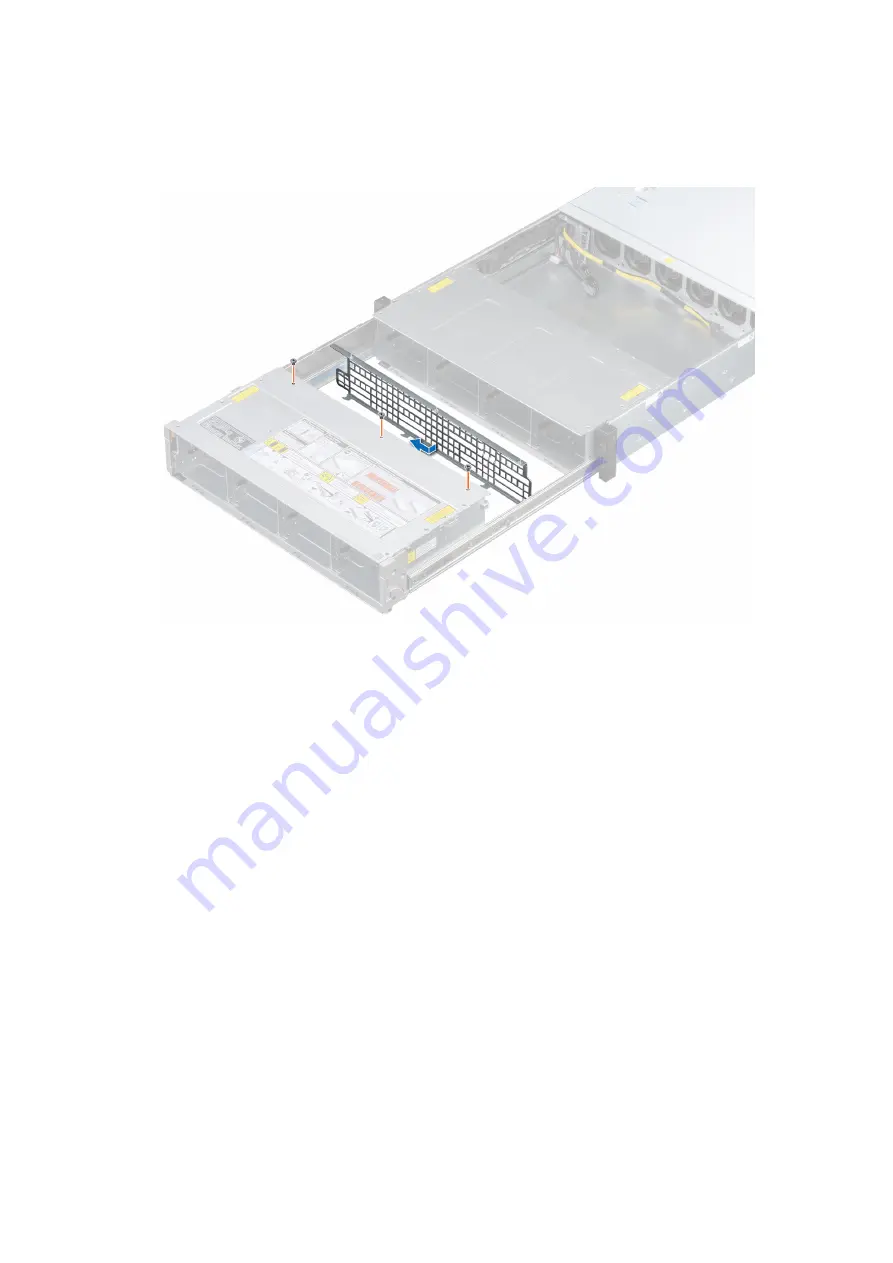
1. Align the backplane bracket with the two slots at the bay base in drive bay 1.
2. Slide the bracket to the left until it is firmly seated and locks into place.
3. Using a Phillips #1 screwdriver, tighten the screws on top of the drive bay to secure the bracket.
Figure 44. Installing bay 1 backplane bracket
Next steps
1.
.
2.
3. If removed,
.
4. Follow the procedure listed in
After working inside your system
Removing the drive bay 2 backplane brackets
Prerequisites
1. Follow the safety guidelines listed in
.
2. Power off the system and all attached peripherals.
3. Disconnect the system from the electrical outlet, and disconnect the peripherals.
4. If installed,
5.
6. Remove the
7. Remove the system from the rack and place it on an ESD work bench. For more information, see the
Rail Installation Guide
at
8.
.
Steps
1. Using a Phillips #1 screwdriver, remove the screws on the top of the drive bay 2, securing the backplane brackets.
2. Disconnect the cables of the cable chain assembly connected to the backplane.
3. Slide the brackets to the right to disengage them from the slots on the bay base in drive bay 2.
4. Lift the right bracket away from the system and move the left bracket away from the drive bay.
Installing and removing system components
63


