


NOTE:
A readily accessible disconnect device that is suitably approved and rated shall be incorporated in the field
wiring.
Input requirements
•
Supply voltage: –(48–60) V DC
•
Current consumption: 32 A (maximum)
Kit contents
•
Dell part number 6RYJ9 terminal block or equivalent (1)
•
#6-32 nut equipped with lock washer (1)
Required tools
Wire-stripper pliers capable of removing insulation from size 10 AWG solid or stranded, insulated copper wire.
NOTE:
Use alpha wire part number 3080 or equivalent (65/30 stranding).
Required wires
•
One UL 10 AWG, 2 m maximum (stranded) black wire [–(48–60) V DC].
•
One UL 10 AWG, 2 m maximum (stranded) red wire (V DC return).
•
One UL 10 AWG, 2 m maximum, green with a yellow stripe, stranded wire (safety ground).
System cover
Removing the system cover
Prerequisites
1. Follow the safety guidelines listed in
on page 65.
2. Turn off the system and all attached peripherals.
3. Disconnect the system from the electrical outlet and peripherals.
4. If installed,
5. Place the system on a flat, stable surface.
Steps
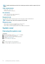
1. Turn the latch release lock to the unlocked position.
2. Press the cover release latch and remove the system cover.
86
Installing and removing system components
Содержание 7CX5T
Страница 21: ...Figure 16 Configuration and layout Dell EMC PowerEdge T640 overview 21 ...
Страница 22: ...Figure 17 Electrical overview 22 Dell EMC PowerEdge T640 overview ...
Страница 23: ...Figure 18 Memory information Dell EMC PowerEdge T640 overview 23 ...
Страница 24: ...Figure 19 System tasks 24 Dell EMC PowerEdge T640 overview ...


