


Hot spare feature
Your system supports the hot spare feature that significantly reduces the power overhead associated with power supply unit (PSU)
redundancy.
When the hot spare feature is enabled, one of the redundant PSUs is switched to the sleep state. The active PSU supports 100 percent of
the system load, thus operating at higher efficiency. The PSU in the sleep state monitors output voltage of the active PSU. If the output
voltage of the active PSU drops, the PSU in the sleep state returns to an active output state.
If having both PSUs active is more efficient than having one PSU in the sleep state, the active PSU can also activate the sleeping PSU.
The default PSU settings are as follows:
•
If the load on the active PSU is more than 50 percent of PSU rated power wattage, then the redundant PSU is switched to the active
state.
•
If the load on the active PSU falls below 20 percent of PSU rated power wattage, then the redundant PSU is switched to the sleep
state.
You can configure the hot spare feature by using the iDRAC settings. For more information, see the iDRAC User’s Guide available at
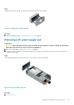
Removing a power supply unit blank
Prerequisites
Follow the safety guidelines listed in
Steps
If you are installing a second power supply unit, remove the power supply unit blank in the bay by pulling the blank outward.
CAUTION:
To ensure proper system cooling, the power supply unit blank must be installed in the second power supply
unit bay in a non-redundant configuration. Remove the power supply unit blank only if you are installing a second power
supply unit.
Figure 41. Removing a power supply unit blank
Next steps
1.
Install the power supply unit blank
.
Installing a power supply unit blank
Prerequisites
1. Follow the safety guidelines listed in
on page 65.
NOTE:
Install the power supply unit (PSU) blank only in the second PSU bay.
82
Installing and removing system components
Содержание 7CX5T
Страница 21: ...Figure 16 Configuration and layout Dell EMC PowerEdge T640 overview 21 ...
Страница 22: ...Figure 17 Electrical overview 22 Dell EMC PowerEdge T640 overview ...
Страница 23: ...Figure 18 Memory information Dell EMC PowerEdge T640 overview 23 ...
Страница 24: ...Figure 19 System tasks 24 Dell EMC PowerEdge T640 overview ...


