


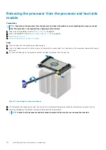


Steps
1. Align the pin 1 indicator of the heat sink to the system board and then place the processor and heat sink module (PHM) on the
processor socket.
CAUTION:
To avoid damaging the fins on the heat sink, do not press down on the heat sink fins.
NOTE:
Ensure that the PHM is held parallel to the system board to prevent damaging the components.
2. Push the blue retention clips inward to allow the heat sink to drop into place.
3. Using the Torx #T30 screwdriver, tighten the screws on the heat sink in the order below:
a. Partially tighten the first screw (approximately 3 turns).
b. Tighten the second screw completely.
c. Return to the first screw and tighten it completely.
If the PHM slips off the blue retention clips when the screws are partially tightened, follow these steps to secure the PHM:
a. Loosen both the heat sink screws completely.
b. Lower the PHM on to the blue retention clips, following the procedure described in step 2.
c. Secure the PHM to the system board, following the replacement instructions listed in this step above. 4.
NOTE:
The processor and heat sink module retention screws should not be tightened to more than 0.13 kgf-m (1.35
N.m or 12 in-lbf).
122
Installing and removing system components
Содержание 7CX5T
Страница 21: ...Figure 16 Configuration and layout Dell EMC PowerEdge T640 overview 21 ...
Страница 22: ...Figure 17 Electrical overview 22 Dell EMC PowerEdge T640 overview ...
Страница 23: ...Figure 18 Memory information Dell EMC PowerEdge T640 overview 23 ...
Страница 24: ...Figure 19 System tasks 24 Dell EMC PowerEdge T640 overview ...


