


UM-0085-B09
DT80 Range User Manual
Page 79
RG
The following three CVs will also be updated:
•
16CV
is the number of under-range samples (<25°C)
•
17CV
is the number of over-range samples (>35°C)
•
18CV
is the total number of samples (sum of 11..17CV)
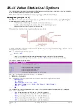
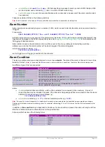
The B schedule will, when polled, report the current histogram data. Polling the C schedule will clear the histogram data.
A typical histogram report would look like:
XB
Under 7
11CV 19
12CV 33
13CV 102
14CV 71
15CV 22
Over 2
Total 246
Rainflow Cycle Counting
Rainflow cycle counting (also called rainflow analysis) is an internationally-accepted method of fatigue cycle counting
used for monitoring long-term accumulative structural fatigue damage. The process reduces large quantities of cyclic
data — collected from sensors attached to the structure over a long period of time — into relatively simple histograms.
As a structure deflects due to repetitive external influences, measurements produce arbitrary peak and valley sequences
that form closed loops or cycles. Each loop or cycle has a size (the difference between peak and valley magnitudes), and
rainflow analysis accumulates a profile of the number of cycles versus cycle size into a histogram.
A minimum cycle size can be defined that sets a noise rejection level, and cycle sizes below this level are rejected as
noise and are not counted. The DT80 implements the ASTM E 1049-85 standard: Standard Practices for Cycle Counting
in Fatigue Analysis.
Real-time rainflow analysis can be carried out using the DT80’s RAINFLOW channel option, which instructs the DT80 to
monitor attached strain gauges at regular intervals and reduce the resulting large quantity of data into simple cycle
histograms.
The DT80 can also produce a formatted report of the accumulated cycle histograms — see
. Although the rainflow cycle counting has been optimized for welded steel structures, it can be used to record
arbitrary waveforms from other sources — temperature cycles in a furnace or electrical signals, for example.
Collecting Rainflow Data
Rainflow analysis is defined by the
RAINFLOW
channel option. Although this is generally used for channels measuring
strain gauge inputs, you can also use it for any type of sensor that is monitoring a process that produces cycles of peaks
and valleys with hysteresis.
The overall range of cycle sizes is divided into a number of smaller cycle size
classes
and, as the analysis proceeds, the
number of cycles of each size class is counted. These counts are accumulated into the DT80’s 32-bit signed
Integer
Variables
(channel type nIV).
Notes:
These integer variables are only for use with rainflow analysis.
The RAINFLOW channel option requires a maximum cycle size to be specified, a noise rejection level, and a range of
sequential integer variables or channel variables that can be used for accumulating the cycle size counts and other
information. It has the form:
RAINFLOW:
a
:
b
:
c
..
d
IV
where:
•
a
is the maximum cycle size expressed in the channel type units (for example, ppm)
•
b
is the minimum cycle size for noise rejection expressed as a percentage of
a
•
c
and
d
denote the range of integer variables (cIV to dIV inclusive) to use for storing count values
Therefore the range of cycle sizes is from zero to the maximum cycle size defined (
a
), and cycle sizes smaller than
b
% of
a
are rejected and not counted. For example, the channel option
(RAINFLOW:1000:5:c..dIV)
sets the cycle size range to 0–1000 units, and cycle sizes less than 50 (5% of 1000) units are rejected as noise.
The number of variables allocated for the rainflow analysis must be set to the number of cycle size classes required over
the cycle size range, plus seven (7) additional variables for summary data. For example, if you require 10 cycle size
classes over the cycle size range then 17 variables will be needed. The variables can begin at any number in their range
of 1 to 500 (c), and are used sequentially to the last variable number (
d
).
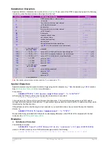
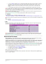
The use of variables in the allocated variable range is summarized in the following table. The first column shows how
variables are used within the allocated range, and the last column shows how 20 variables are used. The last 7 variables
contain various summary data.
Содержание DT80
Страница 29: ...UM 0085 B09 DT80 Range User Manual Page 29 RG The DT80 File System P114 ...
Страница 184: ...UM 0085 B09 DT80 Range User Manual Page 184 RG Figure 71 DT80 communications options ...
Страница 185: ...UM 0085 B09 DT80 Range User Manual Page 185 RG Figure 72 DT80 communications options integrated modem models ...