


UM-0085-B09
DT80 Range User Manual
Page 133
RG
In
DT80
parlance, the former is an
IF
channel, while the latter is an
ALARM
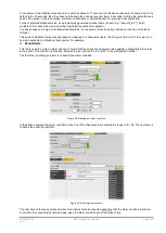
. The
Output text
field specifies the alarm
text, which will be logged to the schedule's alarm store when (or while) the alarm is triggered. Special "substitution
characters" can be included, which will cause the
DT80
to insert certain dynamic values. In the example above, the
?V
and
?U
sequences will be replaced by the channel value and units respectively. The logged alarm string will therefore be
something like:
Temp outside range: 49.2 degC
As well as being logged, the alarm text is also sent to the
DT80
's currently active comms port. If the
Send to Host Port
option is set then it will instead be sent to the host RS232 port, regardless of which port is currently active. This is
typically used for sending modem control messages.
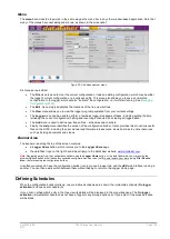
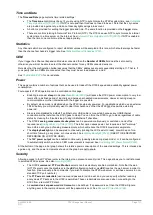
Use the
Action Navigator
to add one or more actions to perform when (or while) the alarm is triggered. These actions
may include:
•
executing a
DT80
command (or string of commands)
•
sending an email message
•
sending an SMS message
•
mirroring the state of the alarm (true or false) on up to two digital outputs or channel variables
Each time an action is added, a panel appears on the right hand side containing details about the action. Adding or
selecting an action will highlight its details panel and allow its settings to be modified.
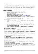
In the example shown in
Figure 34
, three actions have been defined:
•
The
DT80
relay output will mirror the alarm, so it will be closed while the alarm condition is true, open when it is
false. The relay state will be updated each time the channel is evaluated.
•
The command string:
9CV=9CV+1; XD
will be executed, which will increment channel variable 9CV, then
manually trigger schedule D.
•
An email message will be sent to
. The subject of the message will be
Logger Alarm
and the message body will contain the output text, e.g.
Temp outside range: 49.2 degC
.
To remove an action, click the
Delete
button.
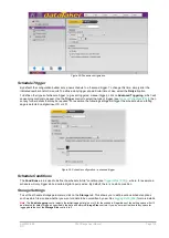
Advanced
The
Advanced
tab contains various other options, which will vary according to the channel type. For example, an analog
channel might include input gain lock settings, while a frequency input channel might have a sample period setting.
For most channel types, data manipulation options (e.g. rate of change) can also be selected here.
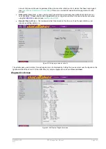
Control Channels
Control channels are outputs, so many of the options to do with sampling or processing the channel return value are not
relevant. Consequently there is only one tab for these channel types.
In the configuration builder, three different digital output channel types are provided (LED driver, Relay driver and Logic
state). These all translate to the logger
DSO
channel type, the only difference between them is in the displayed graphics
for the wiring diagrams and controls. A typical properties pane display for a control channel is shown below.
Figure 31: Defining a control channel
Содержание DT80
Страница 29: ...UM 0085 B09 DT80 Range User Manual Page 29 RG The DT80 File System P114 ...
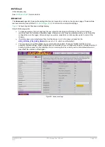
Страница 184: ...UM 0085 B09 DT80 Range User Manual Page 184 RG Figure 71 DT80 communications options ...
Страница 185: ...UM 0085 B09 DT80 Range User Manual Page 185 RG Figure 72 DT80 communications options integrated modem models ...