UM-0085-B09
DT80 Range User Manual
Page 118
RG
Part H –
DT80
Front Panel
The
DT80
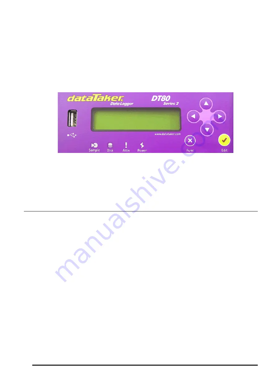
front panel user interface comprises:
•
a 2 line by 16 character back-lit liquid crystal display (not DT81)
•
6 keys (not DT81) –
Up
,
Down
,
Left
,
Right
,
Cancel/Func
and
OK/Edit
•
4 status indicator lights (3 for DT80 Series 1) –
Sample
,
Disk
,
Attn
and
Power
The display provides information about data logger status, channel data, alarms and store operation. In addition the
display will indicate conditions that require attention and USB memory device status.
The
DT80
from cannot be programmed from the front panel. However, pre-defined commands can be issued by
selecting from the function list via the front panel.
Figure 21: DT80 Front Panel
Display
Not applicable to DT81
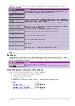
The display normally shows the current value for each channel and alarm in the current job. Each channel or alarm is
shown one at a time. The
Up
and
Down
directional keys on the front panel are used to scroll through the available
channels, as well as various status screens. The channels and alarms are arranged in the same order that they are
defined in for the current job.
Displaying Channels and Alarms
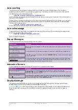
When channel data is displayed, the top line of the display shows the channel identification. The default is the channel
number and type. If channel identification text has been entered as a channel option, then the first 16 characters of that
text is displayed.
The bottom line on the display shows the most recent reading as a numeric value or bar graph. If the channel or alarm
has not yet been sampled, the display shows "
NotYetSet
".
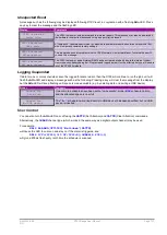
When alarms are displayed the top line of the display identifies the alarm and the state of the alarm – ON or OFF. If the
alarm channel definition includes identification text, then this is displayed when the alarm is not true. If the alarm contains
action text, this is displayed when the alarm is true.
Example
As an example, assume that the following job has been defined:
BEGIN"MYJOB"
RA1M 1TK("Boiler Temp",FF0)
2LM35
ALARM4(3V>2000)"Over voltage"
1CV(W)=1CV+1
ALARM7(4TT("Oven OK")>107)"Oven Over Temp"
END
Содержание DT80
Страница 29: ...UM 0085 B09 DT80 Range User Manual Page 29 RG The DT80 File System P114 ...
Страница 184: ...UM 0085 B09 DT80 Range User Manual Page 184 RG Figure 71 DT80 communications options ...
Страница 185: ...UM 0085 B09 DT80 Range User Manual Page 185 RG Figure 72 DT80 communications options integrated modem models ...


