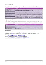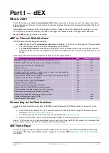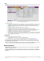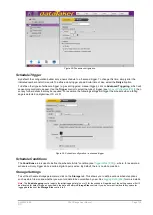
UM-0085-B09
DT80 Range User Manual
Page 137
RG
Time and Date
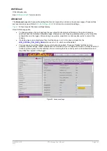
The
Time and Date
page contains time related settings:
•
The
Time zone
control must be set if you are using NTP to synchronise the
DT80
. If NTP is not used then this does not need to be set. Note that the city names
are provided as a guide only, and do not take daylight savings into account.
•
A button is provided for setting the logger date and time. The same function is provided on the
Logger
menu.
•
There are controls relating to Network Time Protocol (NTP). The
DT80
can use NTP to synchronise its internal
system time to a time server on the Internet. See
Automatic Time Adjustment (NTP) (P270)
. If NTP is enabled
then the time zone control must be set appropriately.
Statistics
Any channels which are configured to report statistical values will be sampled at this rate, which should always be faster
than the channel's schedule's trigger rate. See
Statistical Report Schedules (P57)
.
CEM
If your logger has Channel Expansion Modules connected then the
Number of CEMs
field must be set correctly,
otherwise you will not be able to select the channel number for any CEM-connected sensors.
Note also that the configuration builder assumes that the CEMs' addresses are set sequentially starting at 1. That is, if
you specify that two CEMs are connected then they must be set to addresses 1 and 2.
See
for more details.
Power
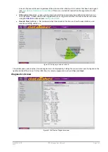
This page contains a number of options that can be used to trade off the
DT80
's speed and availability against power
consumption.
Four aspects of
DT80
operation can be controlled on this page:
•
Enabling low power
sleep
) will reduce the
DT80
power consumption to very low
levels after a defined period of inactivity and between scheduled measurements. However, during sleep no
communications or other interaction with the logger are possible.
•
By default, sleep mode is disabled when the
DT80
is externally powered. For applications which use an external
12/24V battery you will probably want to clear this checkbox, so that the
DT80
can sleep while externally
powered.
•
Sleep is also disabled by default if an Ethernet or USB cable is connected, because any USB/Ethernet
connection will be lost when the
DT80
goes to sleep. You can force the
DT80
to go to sleep regardless of cable
status by clearing the "disable sleep if using USB/ethernet" checkbox.
•
The
DT80
's
analog measurement subsystem
can be powered continuously, or switched on and off as
). The latter option saves power, but requires a short "warm up"
time before each group of analog measurements, which will reduce the
DT80
's maximum sample rate.
•
The
display backlight
can be powered continuously (making the LCD easier to read), or switched on for a
short time following a key press, or not used at all. See
.
(NEED TO BE REVISED
DEPENDING ON LCD TYPE USED)
•
The
12V power output
can be enabled continuously (possibly also during sleep mode), or it can be configured
to automatically switch on when a CEM measurement is required. See
Controlling 12V Power Output (P290)
.
At the bottom of the page, a bar graph shows the relative power consumption of the selected settings. This is intended as
a guide only, and the power increments shown on the graph are not to scale.
Security
Allowing access to the
DT80
's servers via the Internet can present a security risk. This page allows you to restrict access
to selected
DT80
.
•
The
DT80
's
command, FTP
and
Modbus
servers can be selectively enabled or disabled. Note that the web
(HTTP) server cannot be disabled via the
dEX
configuration builder, as
dEX
requires the web server in order to
function. (Use manual profile commands if you wish to disable the
DT80
web server or set these servers to non-
standard TCP port numbers.)
•
The
FTP server credentials
(user name and password) can be set, and you can specify whether read-only
anonymous FTP access to the
DT80
is permitted. These credentials are also used when connecting to the
DT80
from a remote PPP client.
•
A
command server password
and
timeout
can be defined. If a password is set then the
DT80
will ignore
anything sent to the command server until the password is sent. See
.
Содержание DT80
Страница 29: ...UM 0085 B09 DT80 Range User Manual Page 29 RG The DT80 File System P114 ...
Страница 184: ...UM 0085 B09 DT80 Range User Manual Page 184 RG Figure 71 DT80 communications options ...
Страница 185: ...UM 0085 B09 DT80 Range User Manual Page 185 RG Figure 72 DT80 communications options integrated modem models ...

