UM-0085-B09
DT80 Range User Manual
Page 127
RG
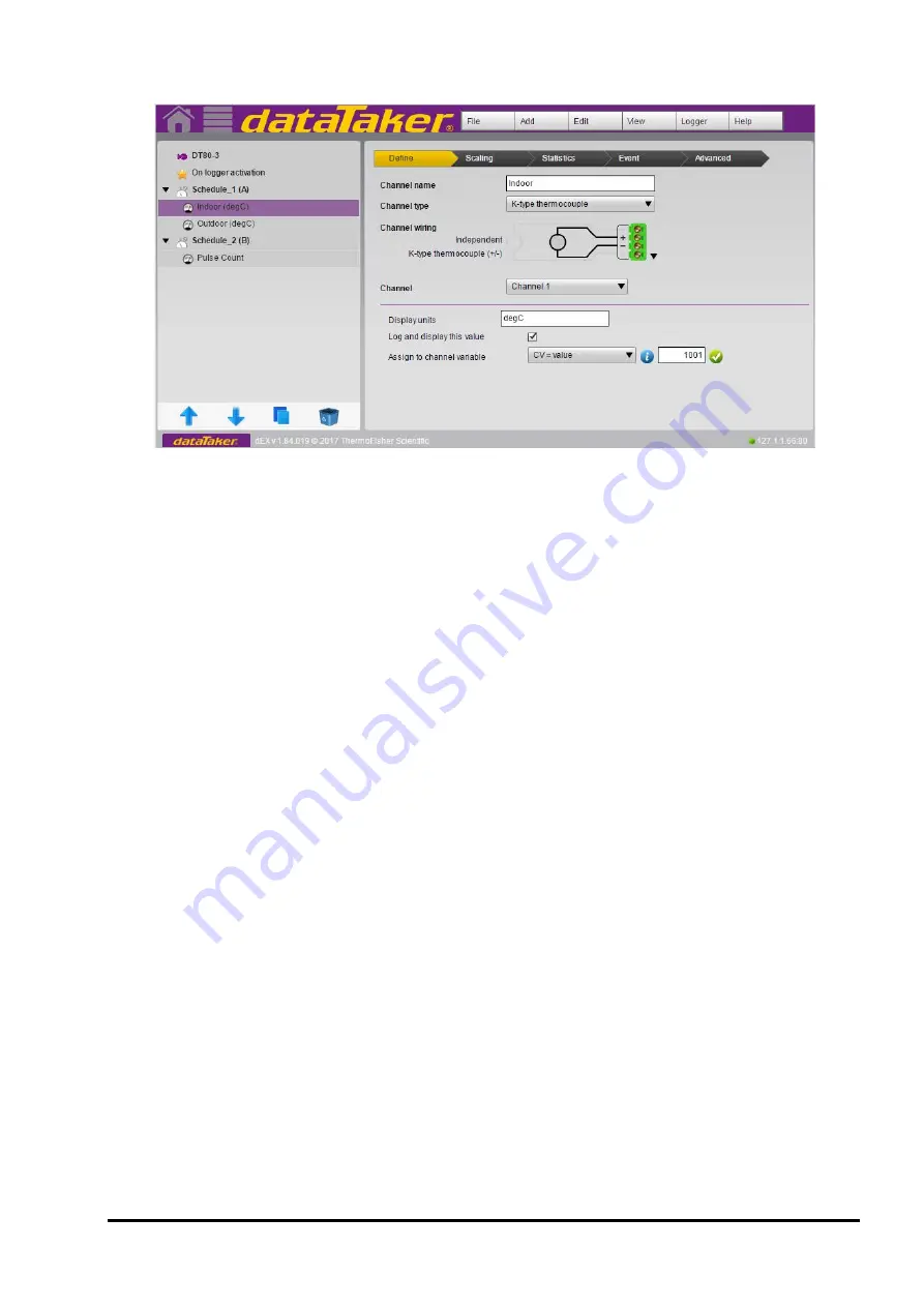
The following screenshot shows the general configuration builder screen layout:
Figure 23: Typical configuration builder display
Tree View
The area on the left of the screen shows a
tree view
of the current configuration. As configuration elements (channels
and schedules) are defined, entries are added to the tree view. This part of the interface thus gives an overview of the
configuration, showing which channels belong to which schedules.
The tree contains three "levels", with each level's entries indented further to the right.
•
At the top level there is a single entry for the logger as a whole. This entry represents the logger's global
settings, such as profile settings and statistical schedule rate.
•
Beneath that are the schedules. In the screenshot three schedules have been defined: the built-in
On logger
activation
entry represents the immediate schedule, and is followed by two user schedules, A and B (a.k.a
"Schedule_1" and "Schedule_2").
•
Finally, at the third level are the channels: in this case, "Indoor", "Outdoor" and "Wind Speed".
If you highlight an entry in the tree, its details will be displayed in the large
properties pane
area which occupies most of
the screen area. The border between the tree view and the properties pane can be dragged left or right to adjust the
width of these two areas.
If you double click on a tree entry, its name will become editable. This allows you to rename an existing schedule or
channel.
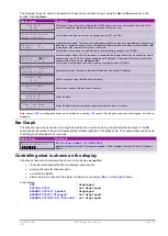
At the bottom of the tree view area are four buttons:
•
The arrow buttons are used to re-order items in the tree by moving the highlighted entry up or down
•
The double rectangle button creates a duplicate of the currently selected channel
•
The Recycle Bin button will delete the highlighted entry
Finally, the small triangles next to the logger and schedule tree view entries can be used to hide/unhide all of their
constituent entries, which can reduce clutter when you are working on a large configuration.
Properties Pane
The large
properties pane
on the right hand side is used to display all of the detailed settings for the selected tree view
item.
The layout of this area varies depending on the type of entry selected on the tree – logger, schedule or channel:
•
If the Logger tree entry is selected, the properties pane shows some basic details of the logger, such as the
model and the number of CEMs connected. This is also the place to set any of the
DT80
's profile settings
•
If a schedule tree entry is selected then details of the schedule's trigger and storage options are shown
•
If a channel entry is selected (as is the case on the screenshot) then in most cases the top part of the properties
pane will show the selected wiring configuration and channel number, while the lower part will feature a number
of tabs containing detailed settings
Содержание DT80
Страница 29: ...UM 0085 B09 DT80 Range User Manual Page 29 RG The DT80 File System P114 ...
Страница 184: ...UM 0085 B09 DT80 Range User Manual Page 184 RG Figure 71 DT80 communications options ...
Страница 185: ...UM 0085 B09 DT80 Range User Manual Page 185 RG Figure 72 DT80 communications options integrated modem models ...


