


Besides moving between locations, the autonomy software must control the state of the machine. State
machines have a defined process flow that transitions from one state to another. State machines define
an initial state, end state, error state, and several intermediate states. A trigger initializes a state machine.
For example, an operator might hit a "start the load" button on the machine. In GUIDE, the next block
might be programming to load the truck mixer, and it may include different actions the mixer goes
through.
Because the sensors used for autonomous machines produce so much data, Danfoss uses data lockers to
store and manage that data. GUIDE blocks reference different data lockers so they can consume the data
they need. Multiple GUIDE blocks can consume from one data locker at the same time.
How Most LiDAR Sensors Work
LiDAR (Light Detection and Ranging) sensors provide obstacle data due to their distance readings. They
are the most common hardware that allows an autonomous machine to see its surroundings.
LiDAR sensors come in many varieties, but most are small enough to fit in a person's hand. Circular LiDAR
scanners spin around and shoot out laser light points, capturing the environment around them like a 360
degree video. Another popular LiDAR is solid state LiDAR, which are square, unmoving, and use one laser
beam to record 3D data. Although cheaper with more reliable readings, they do not have a wide range of
view like the circular LiDAR scanners.
Depending on the type of LiDAR, it may only record the shapes of objects around it, not a traditional
picture with red, green, and blue pixels. Each laser point travels until hitting something reflective, and
then the LiDAR measures the relative distance from itself to the reflective object. Each LiDAR has a digital
fingerprint, so it knows its own light points and will not misread points from a nearby LiDAR.
In circular LiDAR scanners, all the laser points appear in a ring around the LiDAR sensor stacked in rows.
One ring row is known as a channel, so a 64 channel LiDAR means that there are 64 rows of stacked rings.
These LiDARs come with different channel counts, and higher channel counts have more data points with
a clearer picture of the environment. Most circular LiDAR's come in 16, 32, 64, or 128 channels.
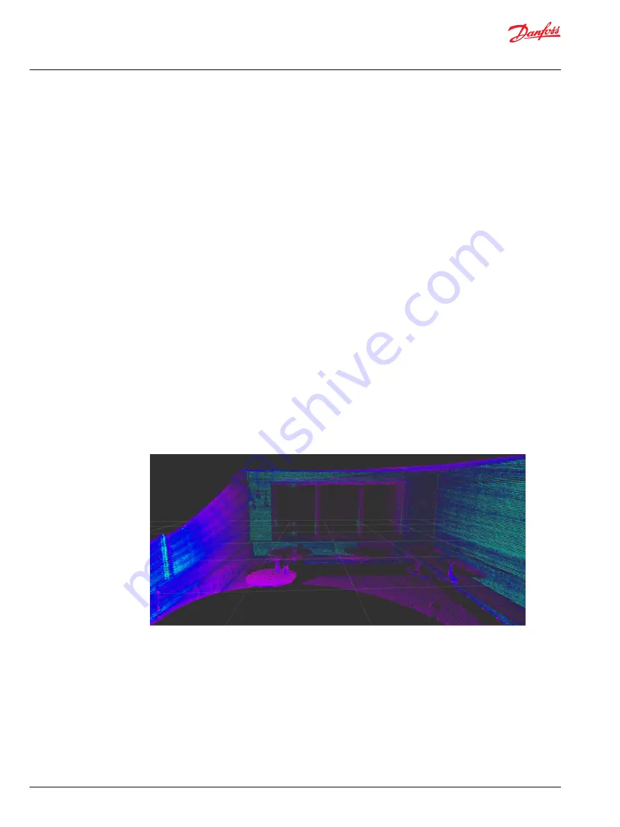
The image above shows objects identified by the circular LiDAR sensor. Each dot is a data point identified
by light reflecting back from the laser, and the points appear in rows of rings around the LiDAR sensor.
The image below shows a photo of the room.
User Manual
Ouster LiDAR
Introduction
6 |
©
Danfoss | March 2023
AQ404281942428en-000103


