


Customize Checkpoint Message Signals
Checkpoint messages describe errors, warnings, and notices during run time. Follow these steps to
customize the names of the checkpoints when using more than one Ouster LiDAR compliance block.
1. Open the Messages page for the first Ouster LiDAR compliance block. For example, go to
Ouster_LiDAR_1 > Checkpoints > Messages.
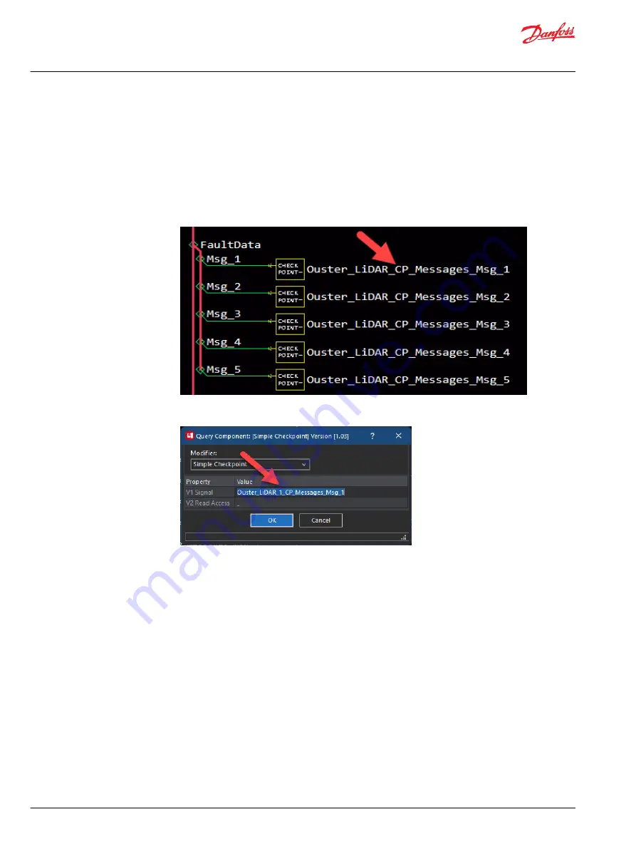
2. Customize the name of each Msg checkpoint.
a) Press Q to enable Query/Change mode.
b) Click on the checkpoint name.
c) Modify the value in the V1 Signal field to match the name of the Ouster LiDAR compliance block.
For example, if the name of the block is Ouster_LiDAR_1, then add "_1" to the name.
d) Click OK.
e) Repeat for the remaining messages.
3. Repeat the name changing steps with the second Ouster LiDAR compliance block. For example, go to
Ouster_LiDAR_2 > Checkpoints > Messages and add "_2" to all the message names.
4. Compile the application.
Hardware Configuration Guidelines
After configuring each Ouster LiDAR compliance block, set up the XM100 and two 32-channel Ouster
LiDAR hardware.
1. Verify the GUIDE application compiled correctly after setting up the software steps.
2. Connect the XM100 to the computer through a CG150 CAN gateway, CS10 wi-fi gateway, or directly
connecting a USB Ethernet.
3. Download the GUIDE application to the XM100. Now the XM100 is ready to act as a DHCP server and
assign IP addresses to other devices in the same local area network (LAN).
4. Use an M12 to RJ45 Ethernet cable to connect the XM100 to Port 1 of the network smart switch. This
assigns the first IP address to the network smart switch. For example, 192,168,1,101.
5. Set up both sets of Ouster LiDAR hardware with their corresponding Ouster Interface Box and power
supply.
User Manual
Ouster LiDAR
Configure Multiple LiDARs
30 |
©
Danfoss | March 2023
AQ404281942428en-000103


