86
•
Z-Trak2 features reference
Z-Trak2 3D Profiler Sensors
GPIO features
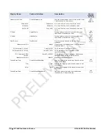
Display Name
Feature & Values
Description
Device
Version
& View
Line Selector
LineSelector
Selects the I/O line.
1.00
Beginner
Line 1
Line1 Encoder Source A+ is on Pin 16, and A
–
is on
Pin 10 of the M12 17-pin I/O connector.
Line 2
Line2 Encoder Source B+ is on Pin 11, and B
–
is on
Pin 1 of the M12 17-pin I/O connector.
Line 3
Line3 GPI 1+ is on Pin 15 and GPI 1
–
is on Pin 14 of
the M12 17-pin I/O connector.
Line 4
Line4 GPI 2+ in on Pin 3 and GPI 2
–
is on Pin 13 of
the M12 17-pin I/O connector.
Line 5
Line5 GPO 1+ is on Pin 8 and GPO 1
–
is on Pin 9 of
the M12 17-pin I/O connector.
Line 6
Line6 GPO 2+ is on Pin 4 and GPO 2
–
is on Pin 5 of
the M12 17-pin I/O connector.
Line Name
lineName
Indicates the name assigned to the selected
line.
1.00
Beginner
DFNC
Encoder Source A
EncoderSourceA Associated with the logical line Encoder Source
A
Encoder Source B
EncoderSourceB Associated with the logical line Encoder Source
B
Input 1
Input1 Associated with the logical line Input 1
Input 2
Input2 Associated with the logical line Input 2.
Output 1
Output1 Associated with the logical line Output 1
Output 2
Output2 Associated with the logical line Output 2
Line Pinout
linePinAssociation
Indicates the pin numbers on the connector
associated to the selected line.
1.00
Guru
DFNC
Pin16=E /
Pin10=EncoderA-
Pin16EncoderApos_Pin10EncoderAneg Pin 16 is Encoder Source A+ and Pin 10 is the
Encoder Source A
–
on the I/O connector.
Pin11=E /
Pin1=EncoderB-
Pin11EncoderBpos_Pin1EncoderBneg Pin 11 is the Encoder Source B+ and Pin 1 is
the Encoder Source B
–
on the I/O connector.
Pin15=GPI1+ /
Pin14=GPI1
–
Pin15pos_Pin14neg Pin 15 is the Input positive signal and Pin 14 is
Input negative signal on the I/O connector.
Pin3=GPI2+ /
Pin13=GPI2
–
Pin3pos_Pin13neg Pin 3 is the Input positive signal and Pin 13 is
the Input negative signal on the I/O connector.
Pin8=GPO1+ /
Pin9=GPO1
–
Pin8pos_Pin9neg Pin 8 is the Output positive signal and Pin 9 is
the Output negative signal on the I/O
connector.
Pin4=GPO2+ /
Pin5=GPO2
–
Pin4pos_Pin5neg Pin 5 is the Output positive signal and Pin 5 is
the Output negative signal on the I/O
connector.
Line Format
LineFormat
Specify the current electrical format of the
selected physical input or output.
1.00
Expert
Opto-Coupled
OptoCoupled The line is opto-Coupled.
LVDS
LVDS The line is LVDS.
Line Mode
LineMode
Indicates if the physical Line is an Input or
Output signal.
1.00
Expert
EncoderSource
EncoderSource The line is an encoder source.
Input
Input The line is an input line.
Output
Output The line is an output line.
Line Status
LineStatus
Indicates the current status of the selected
input or output line.
1.00
Expert


