background image


142  

  Appendix 

Z-Trak2 3D Profiler Sensors 

Model 30 mm measurement range 


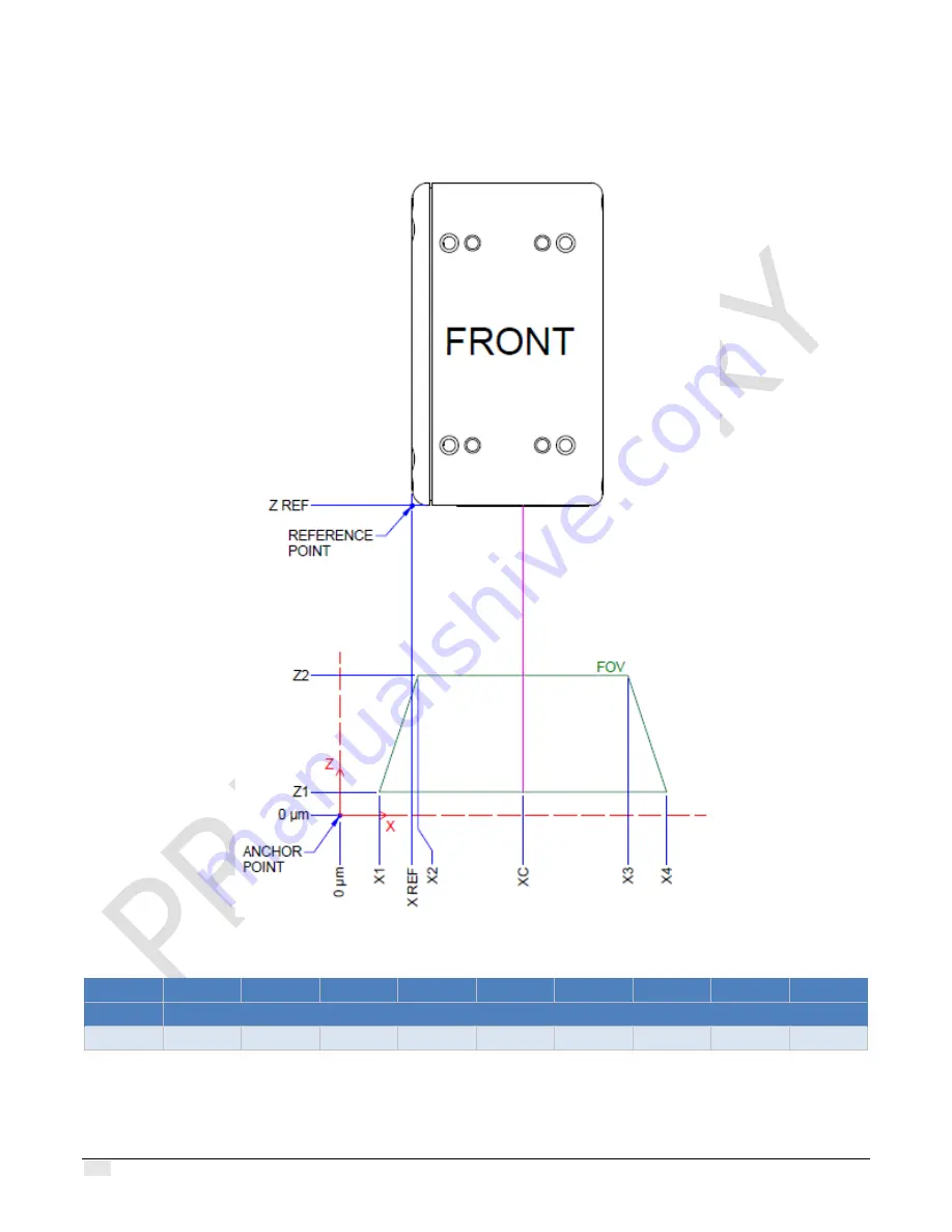
Note that the X Ref point is located between the X1 and X2 offsets. 


Figure 37. Depiction of the anchor point and offsets for the 30 mm range model. Positive Y-axis into the page. 


Z Range 

X1 

X2 

X3 

X4 

XC 

X REF 

Z1 

Z2 

Z REF 


 all values in micrometers 

30 mm 

23900 

33400 

86600 

96100 

60000 

31500 

500 

30500 

74200 


Z Range = Z2 

 Z1          FFOV = X4 

 X1          NFOV = X3 

 X2 

Содержание Z-Trak 2

Страница 1: ... 2 3D Laser Profiler Sensors User s Manual December 22 2021 Rev Preliminary Release 0007 P N 3D L200 UM000 www teledynedalsa com sensors cameras frame grabbers processors software vision solutions 3D imaging ...

Страница 2: ...States and other countries Windows Windows 7 Windows 10 are trademarks of Microsoft Corporation All other trademarks or intellectual property mentioned herein belong to their respective owners Document Date December 22 2021 Document Number 3D L200 UM000 About Teledyne DALSA a business unit of Teledyne Digital Imaging Inc Teledyne DALSA is an international high performance semiconductor and Electro...

Страница 3: ...ATIONS 9 EMI SHOCK AND VIBRATION CERTIFICATIONS 11 Z TRAK2 QUICK START________________________________________ 12 SYSTEM REQUIREMENTS ______________________________________ 14 HOST PC SYSTEM 14 COMPATIBLE GIGE NETWORK ADAPTERS AND SWITCHES 14 THEORY OF OPERATION _______________________________________ 16 HOW A 3D PROFILER SENSOR WORKS 16 DEFINITIONS 17 INSTALLATION ________________________________...

Страница 4: ...figuration file 47 Using a power up configuration 47 MONITORING EVENTS 48 SETTING ACQUISITION PARAMETERS 49 Acquiring a profile 49 Creating a 3D surface view 51 Fixed scan vs variable scan 51 Adjusting laser intensity for optical performance 52 OPTIMIZING PROFILE RATE 53 MULTI SENSOR SYSTEMS ______________________________________ 55 CONNECTING MULTIPLE 3D SENSORS 55 SENSOR SYNCHRONIZATION 55 Featu...

Страница 5: ...ST CONTROLS CATEGORY 109 FILE ACCESS DIALOG CATEGORY 110 File Access Dialog features 110 TECHNICAL SPECIFICATIONS _________________________________ 112 IDENTIFICATION LABEL 112 MECHANICAL SPECIFICATIONS 112 MOUNTING HOLES SPECIFICATIONS 114 ENCLOSURE IP RATING 114 CONNECTORS 114 Data connector Ethernet M12 X coded 8 pin female connector 116 I O connector M12 17 pin male connector 117 Emergency saf...

Страница 6: ...DIX ________________________________________________ 137 Z TRAK2 2K SERIES MODELS 137 Z Trak2 S 2K series 137 Z Trak2 V 2K series 138 REFERENCE POINT ANCHOR POINT AND OFFSETS 139 DEPICTION OF AOI FEATURES 144 FEATURES SAVED IN A CONFIGURATION FILE 147 SHERLOCK OBTAINING A LICENSE 148 CONFIGURING NETWORK ADAPTER NIC FOR GIGE VISION DEVICES 150 Reference documents 150 GigE connection Ethernet Proper...

Страница 7: ...entional less than sec unaided eye exposure Aversion response blink reflex will protect workers from visible lasers unless a telescope or microscope is used Not a skin or materials burn hazard Class 3R CAUTION AVOID DIRECT EYE EXPOSURE Visible lasers of no more than 5 mW continuous wave power through a 7 mm diameter aperture largest pupil aperture Avoid intentional exposure to direct or reflected ...

Страница 8: ... Safety features Emergency shutdown For added safety Z Trak2 units come with external signal pins for an Emergency shutdown switch Even when a Z Trak2 unit is powered the laser will not operate unless a normally closed emergency shutdown switch E STOP is connected to the external safety pins of the sensor A 24 VDC signal must be applied to the E STOP In some global jurisdictions it is possible to ...

Страница 9: ...potential hazards associated with laser use Handling precautions and cleaning instructions Do not handle while the laser is activated or when the device is powered on Mount the profiler before connecting the Ethernet and I O cables See Installation and Technical specifications for mounting information and subsection Connectors for cabling information Clean the laser and image sensor windows carefu...

Страница 10: ...with free powerful software packages All models come in IP67 rated enclosures and are ideal for applications in electronics PCB wafer flat panel factory automation food processing and secondary battery markets Figure 3 The Z Trak2 3D laser profiler The Z Trak2 delivers 2K points per profile with scan speeds up 45 000 profiles sec S 2K series or 10 000 profiles sec V 2K series Its single scan high ...

Страница 11: ...ntuitive graphical interface for rapid setup of multiple Z Trak2 sensors simultaneously Enhanced 3D visualization of profile and surface view from one more sensors simultaneously Third party software support for 3D image processing using GenICam 3 0 3D output formats or 16 bit monochrome output format Compact integrated within a ruggedized protective housing IP67 with tapped and through mounting h...

Страница 12: ...0 Red 660 nm 2M 100 64 5 96 9 185 3 T20 Model in development values subject to change For other laser options contact Teledyne sales Z Trak2 V 2K series This series supports 1 GigE Ethernet Model Laser Color safety rating Measurement Range mm Standoff Distance mm Near FOV mm Far FOV mm Case Size Z TRAK2 V 2K 0004 Blue 405 nm 2M 4 TBD TBD TBD T10 Z TRAK2 V 2K 0015 Blue 405 nm 2M 15 32 7 26 6 32 3 T...

Страница 13: ... M12X R45 8 pin male X coded to RJ45 PoE PoE 5M data cable CEI MI 1 7 L0 05M Power supply 24 V 20 W see note below MEAN WELL MDR 20 24 Mount Contact Teledyne Network cable RJ45 to RJ45 CAT6 Note For multiple profilers use MDR 100 series Contact information of cable and accessories manufacturers is provided below Components Express Inc CEI www componentsexpress com Mean Well www meanwell com ...

Страница 14: ...old separately The Sapera processing Imaging Development Library provides a suite of 3D image processing functions for profiles and range maps Contact Teledyne DALSA Sales Teledyne DALSA Software Platform for Linux GigE V Framework Ver 2 20 01 for X86 or Arm type processor The framework contains lightweight libraries for camera sensor control and image acquisition Available for download http teled...

Страница 15: ...teral X Reflectance R Multipurpose typically peak width W 3D data output formats compatible with GenICam 3 0 SNFC 2 3 Linescan3D RectifiedC UniformX Z CalibratedAC XZ CalibratedACRW XZRW Native values and world measurement units micrometers millimeters inches 16 bit mono 1D line scan mode 8 bit mono 2D area scan mode Reflectance management Time integration Laser power control automatic or manual I...

Страница 16: ...tion Mechanical specifications Enclosure IP rating Conform to IP67 Protection Level IEC Power connection Via I O connector or via Ethernet cable with PoE injector Connectors I O M12 17 pin male Ethernet M12 X coded 8 pin female Electrical Interface Power input voltage Aux power input 20 to 24 V DC max 30 V PoE injector Supports IEEE 802 3at PoE type 2 PoE max voltage 57 V DC Input outputs 2 inputs...

Страница 17: ...Z Trak2 3D Profiler Sensors Z Trak2 2K Series common specifications 11 EMI shock and vibration certifications Pending ...

Страница 18: ...5 GigE NETGEAR MS510TX Power supply 24 V 20 W if not using PoE switch Mean Well MDR 20 24 for single device setup Network cable RJ45 to RJ45 CAT 6 required 2 DOWNLOAD 3 INSTALL SAPERA LT Sapera LT SDK https www teledynedalsa com en products imaging vision software sapera lt download Z Trak2 Firmware Download Z Trak2 firmware Double click SaperaSDKSetup exe You will be asked to reboot at some point...

Страница 19: ...13 6 START SAPERA Z EXPERT desktop icon or Start menu Teledyne DALSA Sapera LT If permitted by local regulations 7 UPDATE Z TRAK2 FIRMWARE 5 Drag and drop 6 Grab or snap 3 Set Laser Safety Internal to disable E STOP 4 Turn laser on 1 Select 2 Expand ...

Страница 20: ...mpatible GigE network adapters and switches V 2K series 1 Gb Ethernet 1 GigE S 2K series 5 2 5 or 1 Gb Ethernet 5 2 5 or 1 GigE CAT 6 Ethernet cable 10 100 Mb Ethernet is not supported by the Z Trak2 series of profilers The Status LED will show that it acquired an IP address solid Blue but Z Trak2 will not function at these slower connections Compatible GigE network adapters and switches Network d...

Страница 21: ...rable devices ASUS XG C100C Switches Switches offer a range of functions and performance grades so care must be taken to choose the right switch for a particular application A switch is required if the profiler to PC separation is greater than 100 meters It is recommended to test network device performance since certain devices may not achieve acceptable results in actual operation depending on th...

Страница 22: ...nts at a very high rate Figure 4 The Z Trak2 3D laser profiler showing the laser window and the 2D sensor window Z Trak2 illuminates an object with a plane of light The light reflected by the projected line on the object is captured on the 2D sensor which forms a profile After determining the position of the laser line reflected on the area sensor the profiler uses triangulation to precisely trans...

Страница 23: ...es a sequence of profiles the output forms a range map The Z Trak2 data output mainly consists of the height value for every point of a scan But other information can also be captured such as reflectance See section 3D Data Type output format description for details on data output formats Definitions The figure below depicts the different axes distances and regions the terms used in the figure and...

Страница 24: ...ical axis where height measurements are made It is perpendicular to the XY plane Measurements can be made on only a portion of the Z axis called the Z range Y Axis The Y axis is the axis of the scan or travel direction Standoff distance The standoff distance also known as the clearance distance is the minimum distance from the profiler s laser exit window where measurements can be made This distan...

Страница 25: ...asurement section midway between the near FOV and far FOV Note that for the Z Trak2 family sensors the laser line extends beyond the FOV however the factory calibration ensures that Z measurements can take place in the entire trapezoidal region delimited by the FOV in the XZ plane see measurement area definition Measurement area The measurement area is the trapezoidal region in the XZ plane that i...

Страница 26: ...sensors to move instead of the object For correct measurements the profile sensors must be installed such that it is parallel to the path of motion Use the following guidelines for a correct setup The X Y and Z axes must be at right angles A unit must be mounted so that it is parallel to the path of travel conveyor XY plane the X axis laser line is perpendicular to the scanning direction and the Z...

Страница 27: ...urement results Z Trak2 profiler is designed to dissipate heat through its housing As such ensure that it is mounted on a heat conductive metallic structure and that the entire surface of one of the sides of the housing makes full contact with the conductive surface See section Temperature management for details Figure 9 An example of mounting setup The two metallic mounts will help dissipate heat...

Страница 28: ...vary for different models Z Trak2 Mounting Planning machine opening space Connector length cable bend radius enclosure height height of Z Trak2 casing working distance and height of the measurement area determine the minimum machine opening required for installation The figure below depicts the machine opening space required for an object placed within the measurement area The height should be cal...

Страница 29: ...10 Machine opening space example The green rectangle depicts the maximal height of the opening space when the target object is placed farthest from the 3D sensor The object must be placed within the measurement area The working range corresponds to the Measurement AOI Height feature starting at the working distance Figure 11 Depth required depends on the body enclosure length connector length and ...

Страница 30: ... Acquiring quality profiles entails planning for unwanted laser light reflections or acquisition blockages The following examples depict a few potential issues to consider Blocked measurement area Consider cases where the image sensor may not have complete visibility over the required scan range The scan direction may need to be reversed or the object may need to be scanned in two opposite directi...

Страница 31: ...reflection angles away from entering the profiler s image sensor window Profiler positioning is dependent on the scanning situation Figure 14 Reflective surfaces or objects with oddly angled surfaces may scatter the laser light back into the 2D sensor window creating blurred profiles Controlling ambient illumination Over its image sensor window the profiler uses a narrow bandpass optical filter th...

Страница 32: ...ons so that the laser line profiles are distinctly detected Powering Z Trak2 with PoE A PoE injector or a PoE Ethernet switch can be used to power Z Trak2 devices The picture below uses a PoE Ethernet switch One or more Z Trak2 units can be powered using an Ethernet switch Connect power via the I O or PoE not both Although Z Trak2 has protection differences in ground levels may cause operational i...

Страница 33: ...installation setup when using I O cable to power the profiler Operating conditions Temperature management Z Trak2 profilers are designed to optimally transfer internal component heat to the outer metallic body Heat management is achieved by mounting the profiler with metal screws onto a metal structure that conducts heat which will act as a heatsink via its mounting screw holes and by providing th...

Страница 34: ...faults due to electrostatic discharge ESD Ensure Z Trak2 housing is securely connected to earth ground to avoid damage to the device or intermittent failures during normal operation Teledyne DALSA has performed ESD testing on profilers using a 4 kV ESD contact generator and 8 kV in air generator without any indication of operational faults To prevent ESD problems follow these guidelines Mount the ...

Страница 35: ...ramework Both Sapera LT SDK and GigE V Framework packages are available for download from Teledyne DALSA website www teledynedalsa com This section discusses installation steps for Sapera LT Installing Sapera LT SDK The Sapera LT SDK version 8 61 or later development software provides everything you need to configure the Z Trak2 profiler and acquire data in your applications It includes the Sapera...

Страница 36: ...ice found Network connection Make sure Z Trak2 is powered before proceeding refer to Powering Z Trak2 with PoE or Powering Z Trak2 using the I O connector To connect Z Trak2 to the host computer 1 Connect the Z Trak2 unit to the host computer GigE network interface card NIC using the M12 X coded to RJ45 Ethernet cable If connecting Z Trak2 through a network switch connect the Z Trak2 to the switch...

Страница 37: ...es found by your computer Once the Z Trak2 is connected and has been assigned an IP address its Status LED is steady blue the GigE Server icon will indicate that the device was found It might take a few seconds for the GigE Server to refresh its state after an IP address is assigned Note that the GigE Server periodically scans the network to refresh its state Right click the GigE Server icon then ...

Страница 38: ...orwards incoming packets from the NIC to the GigE Vision driver if they contain image data otherwise the packets are passed through to the host It must be enabled for GigE devices MaxPktSize Corresponds to the packet size in bytes that the device supports Value is 0 if not connected ABI Application Binary Interface Version of the interface exported by the filter driver Device IP error Sometimes th...

Страница 39: ...dy Blue IP address assigned No application connected to the profile sensor Steady Green Application connected Flashing Green Acquisition in progress Laser LED This amber color LED is ON when the laser is ON laser activated and E STOP is bypassed Range LED TBD Z Trak2 firmware If a firmware update is required Teledyne DALSA will provide the appropriate file See section Updating firmware via File Ac...

Страница 40: ...ties page On the Advanced tab configure the following parameters as indicated Enable Jumbo Packets Jumbo Frames Enable Flow Control choose Rx and Tx Enabled Enable Interrupt Moderation Choose an Interrupt Moderation Rate Extreme or Off Disable Large Send Offload IPv4 Maximize Receive Buffers and Buffer Descriptors if available Adjust the Receive Side Scaling Queue for best performance for processi...

Страница 41: ...tain switches might perform better using a packet size of 4096 bytes instead of 9000 bytes In addition with TurboDrive a smaller to mid size packet usually outperforms a larger packet size Some Ethernet switches may produce more Pause Frame requests than expected when Jumbo Frames is enabled Changing the Ethernet Packet Size may minimize Pause Frame requests from such a switch and improve overall ...

Страница 42: ...p refer to the Network Imaging Package for Sapera LT Optimization Guide Using Z Trak2 with supported third party software packages If Z Trak2 is used in a third party GigE Vision compliant environment refer to the appropriate application note for the supported packages for installation details 3D L AN0002 Using Z Trak with MVTec HALCON HDevelop Please contact tech support or visit website applicat...

Страница 43: ...ure up to 16 sensors in a variety of topologies using user defined alignment targets See also chapter Multi sensor systems The Z Expert context sensitive help opens in a browser is available using the F1 key from anywhere in the interface Please refer to it for detailed information on the use of Z Expert as this chapter offers an overview of the application Overview of Z Expert GUI Z Expert interf...

Страница 44: ...38 Introduction to Z Expert Z Trak2 3D Profiler Sensors Toolbar The toolbar provides quick access to often used commands ...

Страница 45: ...s to display Manage a multi sensor system Features Browser and Features Description The Features Browser pane allows viewing or changing the features parameters supported by the acquisition sensor Features are organized by categories available categories and features are sensor dependent Many of the features are always modifiable some are read only and others may be changed depending on other sett...

Страница 46: ...ng will be shown in the parameter list Choose the visible parameters according to the level required for use with the Parameter visibility list You can choose among Beginner Expert Guru Load or save parameter settings Update the sensor firmware See section Updating firmware via File Access Dialog Console Messages The Console Messages pane displays displays information warning and error messages ge...

Страница 47: ...lows you to select among a series of events to monitor which can also be logged Display pane The display pane renders the result of a grab or snap The pane may display up to 9 concurrent views Select the number of views from the Z Expert toolbar A menu within each view can be used to change display settings ...

Страница 48: ... the profile or measurement AOI Tips Put the pointer on the profile to display the X and Z values Use the mouse wheel to zoom in or zoom out the profile Drag the profile to change its location in the window The measurement AOI from the above capture was reduced The dotted area represents the measurement area The measurement AOI can be reduced in the Z axis Here the height of the AOI was reduced An...

Страница 49: ...ors in dotted red that you can adjust The color of the distance cursors can be changed from the menu for a better view Tip To show the distance cursors click the Toggle Distance Cursor icon at the bottom left of the view Put your pointer on a cursor line to display the distance between the two parallel cursor lines ...

Страница 50: ... rotate the surface around the rotation point in the display plane Use Alt click to change the location of the rotation point Use the different handles to change the proportions of the surface Click the 4 arrows icon at the bottom display 1 to reset the view Click XY XY XZ XZ YZ or YZ to display your surface in the chosen plane display 2 Drag the XYZ axes at the bottom left of a view window to rot...

Страница 51: ...ected to the network The default value for the device user ID of a profiler is its serial number To change the Device User ID feature select the Profile Management category Tip Use a descriptive easy to remember name or its location in a system such as Top View and Bottom View Updating firmware via File Access Dialog Download the latest firmware for the Z Trak2 from the Teledyne website To update ...

Страница 52: ...device or in a configuration file ccf camera configuration file Power up settings are used when the 3D sensor powers up or is reset The settings are saved in non volatile memory on the profiler itself There are 3 feature sets one is the default factory setting and the other two are user settings Users can choose a default power up configuration load a previously saved configuration or save their c...

Страница 53: ...Save CCF 3 Choose a location and filename then click Save The configuration is saved in a file with a ccf extension To load Z Trak2 settings from a file To load a saved configuration choose Load CCF from the device shortcut menu and select a ccf file Using a power up configuration In the Profiler Management category next to Power up Configuration click Press Figure 18 Power up dialog for choosing ...

Страница 54: ...SetSelector To reset the device to the factory configuration select Factory Setting and click Load Configuration To restore a saved configuration select the appropriate user set and click Load Configuration To save the current device configuration select UserSet 1 or UserSet 2 and click Save Configuration Monitoring Events Z Expert provides a dialog to easily monitor common events in real time Fro...

Страница 55: ...ill be shown in red a Warning in yellow Setting Acquisition parameters Below are examples of settings you can use to test your Z Trak2 laser profiler with Z Expert Make sure the Features Browser is open Acquiring a profile How to acquire a single profile 1 From the Z Expert Sources Explorer select one or more detected sensors 2 In the Data Output category of the Features Browser set Profiles per S...

Страница 56: ...tion to On activated continuously or Strobed activated during acquisition only 5 Click on an icon next to the sensor to start acquisition start stop acquisition snap 1 or snap multiple 6 Drag and drop a sensor on the display area to view the result of the acquisition ...

Страница 57: ... a single buffer A scan can be configured by setting the value of the profilesPerScan feature to greater than 1 see Data Output features Figure 19 Acquisition of multiple profiles of a fixed object Note the buffer in the bottom right corner of the display view Fixed scan vs variable scan The number of profiles can be determined in advance fixed or not variable ...

Страница 58: ...the object being scanned rests or by the moving 3D sensor mount Movement is in the scan direction Y axis See Trigger Input features and Encoder Input features Adjusting laser intensity for optical performance Setting laser intensity for best measurement is the result of a balance between laser power exposure time gamma and HDR high dynamic range settings The goal is to produce an image with reflec...

Страница 59: ...s or more In the Format subcategory set the 3D Data Type output format to UniformX Z or to XZ In the GigE Vision Transport Layer category verify that the Device Link Speed value is 1000 2500 or 5000 Mbps or higher according to model This is the speed negotiated by the network interface The value is read only Verify that the Packet Size value is above 1500 bytes ideally 4000 or 9000 bytes which ind...

Страница 60: ... equipment between your device and the host computer see Compatible GigE network adapters and switches Section Configuring network adapter NIC for GigE Vision devices in the Appendix provides info about how to configure the network adapter Refer also to the Network Imaging Package for Sapera LT Optimization Guide found from the Start menu in the Teledyne DALSA folder ...

Страница 61: ...o it Profiles may be processed on the same or on different hosts Sensors part of a unified measurement space UMS Units must be attached to the same switch and a single host must do the acquisition and merging The units will typically be synchronized Sensor synchronization Sensor synchronization is used to coordinate the profile acquisition of a group of sensors so that they are triggered simultane...

Страница 62: ...ger Delay Trigger Delay Slave2 Exposure Sequential Acquisition Group Trigger Delay Group Trigger Delay Mode Master and Slaves Figure 21 The external internal signal triggers the master sensor The Group Trigger Delay value determines the earliest time at which the sensors can start exposure The Trigger Delay value of each sensor is different in a sequential acquisition External Internal Signal Expo...

Страница 63: ...gger Delay TriggerDelay Line Selector LineSelector Line Inverter LineInverter Synchronizing with the wizard To help with parameter settings Z Expert provides a Synchronization wizard that sets parameters in all included sensors to prepare them for acquisition Only a few parameters need to be set by the user Sequential acquisition settings In Multiplex mode profiler sensors are triggered in sequenc...

Страница 64: ...r External Trigger The wizard will determine the exposure time and Master Sync Delay Group Trigger Delay to optimize acquisition given the Trigger Rate Group Trigger Delay allows for messages to be received by the slave sensors The trigger delay of the master sensor will be set so it is triggered with the slave sensors Manual acquisition settings In this mode all values must be provided it is up t...

Страница 65: ... external On On On Trigger Start Source Depends on Trigger Enable parameter If Off the internal clock is used to trigger acquisition at the specified Profile Rate If On various sources can be used including counter timestamp modulo encoder etc The profile trigger is generated by the multi sensor sync Various sources can be used including counter timestamp modulo encoder etc The profile trigger is ...

Страница 66: ...es Care should be taken in this mechanical alignment because if the sensor planes are not properly aligned before the calibration process the produced output data will be erroneous Calibration This stage creates the UMS using a calibration target object placed in the measurement area of the sensors A wizard available in Z Expert is designed for this purpose Once this calibration is done all sensor...

Страница 67: ...quired to accurately define the prism These should be provided by the manufacturer In a side by side layout a flat smooth and rigid object that spans the entire width of the combined measurement area in the XZ plane can be used In this case its precise dimensions are irrelevant Creating a UMS Z Expert provides a wizard to help create the UMS for common sensor layout such as ring or side by side or...

Страница 68: ... View Indicates for each feature the device software functional level number in which the feature was introduced different from the firmware revision number Features added after the initial release are in green whether the feature is a member of the GenICam Standard Features Naming Convention SFNC tag not shown or of the DALSA Features Naming Convention DFNC The visibility level in which the featu...

Страница 69: ...eatures Display Name Feature Name Values Description Device Version View Product Model DeviceModelName Displays the device model name 1 00 Beginner Firmware Version DeviceFirmwareVersion Displays the currently loaded firmware version number Firmware files have a unique number and have the cbf file extension 1 00 Beginner Serial Number DeviceSerialNumber Displays the factory set serial number of th...

Страница 70: ...erSetLoad Loads the configuration set specified by the User Set Selector feature to the device and makes it active 1 00 Beginner Save Configuration UserSetSave Saves the current device configuration to the user set specified by the User Set Selector feature The user sets are located on the device in non volatile memory 1 00 Beginner Device Acquisition Type deviceAcquisitionType Displays the Device...

Страница 71: ...aveMemoryError Device ran out of memory while saving set UserSetSave command failed SaveFileError Internal file I O error UserSetSave command failed SaveInvalidSetError An invalid user set was requested UserSetSave command failed SaveResourceManagerError An internal error happened related to the resource manager Built In Diagnostics features Display Name Feature Values Description Device Version V...

Страница 72: ...re of the selected source in degrees Celsius 1 00 Guru Info features Display Name Feature Values Description Device Version View Manufacturer Name DeviceVendorName Displays the device vendor name 1 00 Beginner Product Family DeviceFamilyName Displays the device family name 1 00 Beginner Device Version DeviceVersion Displays the device version This tag will also highlight if the firmware is a beta ...

Страница 73: ...he laser If the Emergency Laser Stop is Active The laser will not turn on 1 00 DFNC Beginner Off Off Turns the Laser Off On On Turns the Laser On The laser will power up only if the Emergency Stop is in the Inactive state Strobed Strobed The laser will be turned on for the duration of the Profile Exposure Time The laser will power up only if the Emergency Stop is in the Inactive state Laser Contro...

Страница 74: ...MinPower Laser Automatic Minimum Power 1 00 DFNC Expert Laser Automatic Maximum Power laserAutoMaxPower Laser Automatic Maximum Power 1 00 DFNC Expert Profile Rate Hz profileRate Specifies the profile rate of the sensor in Hz 1 00 DFNC Beginner Profile Exposure Time in us ExposureTime Sets the exposure time in microseconds when the Exposure Mode feature is set to Timed 1 00 DFNC Beginner Reflectan...

Страница 75: ...ice Version View Points Per Profile pointsPerProfile Number of points in the profile This feature is editable when Uniform X Points Per Profile Mode is set to Manual Otherwise this feature is read only 1 00 DFNC Beginner Profiles Per Scan profilesPerScan Height of the virtual image provided by the device in profiles 1 00 DFNC Beginner Scan Rate Hz scanRate Specifies the device internal frame rate ...

Страница 76: ...e profile median filter 1 00 DFNC Guru Off Off Off On3x1 On3x1 3x1 Median Filter On5x1 On5x1 5x1 Median Filter On7x1 On7x1 7x1 Median Filter Profile Convolution Mode profileConvoMode Selects the mode for the profile convolution filter 1 00 DFNC Beginner Off Off Off On3x1 On3x1 3x1 Convolution Filter On5x1 On5x1 5x1 Convolution Filter On7x1 On7x1 7x1 Convolution Filter Profile Convolution Coefficie...

Страница 77: ...Areascan Areascan Device outputs 2D area scan images 3D Data Type Scan3dOutputMode Selects 3D output data format default is UniformX Z 1 00 Beginner UniformX Z RectifiedC Each profile consists of calibrated Z values in a 16 bit data format The Z values have been resampled to a uniform sampling pattern in the X direction XZ CalibratedAC Each profile consists of calibrated X and Z values in a 32 bit...

Страница 78: ...ormat PixelFormat Pixel formats as defined by the GeniCam standard 1 00 Guru Monochrome 8 Bit Mono8 Monochrome 8 Bit data format Only available in Areascan mode 3D Coordinate Z 16 bit Coord3D_C16 3D Coordinate Z position 16 Bit 3D Coordinate XZ 32 bit Coord3D_AC16 3D Coordinate X and Z positions stored in a 32 Bit value 3D Coordinate XZRW 64 bit Coord3D_ACR016 3D Coordinate X and Z positions Refle...

Страница 79: ... the measurement AOI This is the minimum height value that can be measured 1 00 DFNC Beginner Measurement AOI Height aoiHeight Specifies the height of the measurement AOI 1 00 DFNC Beginner Near FOV Start X aoiNFOVStartX Specifies the horizontal start of measurement AOI at the near FOV 1 00 DFNC Beginner Near FOV Width aoiNFOVWidth Specifies the width of the measurement AOI at the near FOV 1 00 DF...

Страница 80: ...he mechanical height of the device 1 00 DFNC Expert Standoff Distance standoffDistance Standoff Clearance Distance indicates the distance from the laser window of the device to the top of absolute measurement AOI 1 00 DFNC Expert Working Distance workingDistance Working Distance indicates the distance from the laser window of the device to the top of resized measurement AOI 1 00 DFNC Expert AOI Ad...

Страница 81: ...ofileMode Selects how the Points Per Profile will be determined When set to UseMeasurementAOI the Points Per Profile will be calculated based on AOI settings When set to Manual the user must set the Points Per Profile value 1 00 DFNC Guru Use Measurement AOI UseMeasurementAOI Uses the width of the MeasurementAOI to determine the number of points per profile Manual Manual The number of Points per p...

Страница 82: ...ame Drop Count internalAcquisitionFrameDropC ount Indicates the number of 2D frames dropped from the image sensor in areascan mode to respect the maximum GigE transfer bandwidth This preserves the image sensor settings like Exposure Time to be the same as when in Linescan3D 1 00 DFNC Guru Effective Transfer Frame Rate Hz resultingTransferFPS Indicates the transfer frame rate based on the current I...

Страница 83: ...elect the signal source for Encoder Input A 1 00 Expert Line 1 Line1 Encoder A input is Input Line 1 Encoder Source B EncoderSourceB Select the signal source for Encoder Input B 1 00 Expert Off Off Encoder Source B is off Line 2 Line2 Encoder B is Input Line 2 Helps determine position of the encoder and direction of the motion Encoder Mode EncoderMode Indicates the Encoder modes 1 00 Expert High R...

Страница 84: ... in the forward direction Phase A leads Phase B Encoder Reverse EncoderDown The encoder is moving in the reverse direction Phase B leads Phase A Encoder Idle EncoderIdle The encoder is not moving Encoder Reset EncoderReset Resets the Encoder Value to 0 1 00 Expert Encoder Value EncoderValue Indicates the current encoder counter value In quadrature mode the Encoder value automatically increments in...

Страница 85: ...ption Device Version View Direction Direction In quadrature mode The profile triggers are only generated when the motion of the encoder is in the same direction set by the Encoder Direction feature Any Direction AnyDirection Profile triggers are generated regardless of the direction of motion ...

Страница 86: ...r that starts the capture of a profile Variable Scan VariableScan Selects the Variable Scan trigger Trigger Start Source and Trigger Stop Source determine the length of the scans Fixed Scan FixedScan Selects the Fixed Scan trigger Scan Per Trigger feature sets the number of scans to capture Trigger Enable TriggerMode Turns the selected Trigger On or Off 1 00 Beginner Off Off The selected trigger i...

Страница 87: ...oes from high to low Rising Edge RisingEdge The trigger is considered valid when the line source signal goes from low to high Any Edge AnyEdge The trigger is considered valid for any transition on the line source signal Level High LevelHigh The trigger is considered valid while the line source signal is high Trigger Overlap TriggerOverlap Selects if a new trigger will be accepted or latched while ...

Страница 88: ...ggers accepted per second at current exposure time 1 00 DFNC Guru Profile Trigger Frequency profileTriggerFrequency Reads the number of profile triggers sent to TriggerSelector Profile Trigger per second 1 00 DFNC Guru Scan Trigger Status frameBurstState Indicates the current status of Scan Trigger signal 1 00 DFNC Expert Inactive Inactive The scan is waiting for a trigger or the grab to start Act...

Страница 89: ...c All slave sensors must have their Trigger Source set to Multi Sensor Sync Only one master is allowed per Multi Sensor Sync Group 1 00 DFNC Expert Off Off Turns Off multi sensor synchronization On On Turns On synchronization between multiple sensors Sync Status multiSensorSyncStatus Indicates if the selected device is a multi sync master or a slave 1 00 DFNC Expert Master Master Indicates the dev...

Страница 90: ... Trigger Delay Mode specifies whether this delay applies only to slave sensors or to both master and slave sensors 1 00 DFNC Expert Group Trigger Delay Mode multiSensorSyncDelayMode The Group Trigger Delay Mode specifies the sensors to which the Group Trigger Delay applies 1 00 DFNC Expert Slaves Only SlaveOnly Slaves only Master and Slaves All Master and slaves GPIO Control category The Z Trak2 G...

Страница 91: ...Z Trak2 3D Profiler Sensors Z Trak2 features reference 85 ...

Страница 92: ...Indicates the pin numbers on the connector associated to the selected line 1 00 Guru DFNC Pin16 EncoderA Pin10 EncoderA Pin16EncoderApos_Pin10EncoderAneg Pin 16 is Encoder Source A and Pin 10 is the Encoder Source A on the I O connector Pin11 EncoderB Pin1 EncoderB Pin11EncoderBpos_Pin1EncoderBneg Pin 11 is the Encoder Source B and Pin 1 is the Encoder Source B on the I O connector Pin15 GPI1 Pin1...

Страница 93: ...robe light Pulse on End of Exposure PulseOnEndofExposure Generate a pulse on the ExposureEnd event This option is typically used to trigger a strobe light Pulse on Start of Readout PulseOnStartofReadout Generate a pulse on the ReadoutStart event Pulse on End of Readout PulseOnEndofReadout Generate a pulse on the ReadoutEnd event Pulse on Valid Frame Trigger PulseOnValidFrameTrigger Generate a puls...

Страница 94: ...ntrolled 1 00 Beginner DFNC Active Active Sets the output state to active Inactive Inactive Sets the output state to inactive Output Line Software Latch Control outputLineSoftwareLatchControl When Off the selected output line is set with the value in Output Line Value 1 00 Guru DFNC Off Off Output pin state set by outputLineValue Latch Latch Output pin state set by outputLineSoftwareCmd Line Statu...

Страница 95: ...Z Trak2 3D Profiler Sensors Z Trak2 features reference 89 Event category The Event category is used to configure the device event related features ...

Страница 96: ... the timestamp counter into the timestamp buffer 1 00 Expert DFNC Line Start LineStart The timestamp is latched on profile trigger Timestamp Reset Source timestampResetSource Specifies the internal signal or physical input line to use as the timestamp reset source 1 00 Expert DFNC None None No timestamp reset source is specified Note that the Timestamp reset command can still reset the counter Lin...

Страница 97: ...ntrol channel when all previous active events have been disabled because the device cannot send them fast enough generating in internal message overflow All required events must be re enabled manually Event Notification EventNotification Enable Events for the event type selected by the EventSelector feature 1 00 Expert Off Off The selected event is disabled On On The selected event will generate a...

Страница 98: ...uru Profile Trigger Event Timestamp EventLineStartTimestamp Timestamp of the Event Profile Trigger event 1 00 Guru Valid Profile Trigger Event ID EventValidLineTrigger Generate an event on valid profile trigger 1 00 Guru Valid Profile Trigger Data EventValidLineTriggerData Data of the valid profile trigger event 1 00 Guru Valid Profile Trigger Event Timestamp EventValidLineTriggerTimestamp Timesta...

Страница 99: ...Line4 falling edge event 1 00 Guru Line4 Falling Edge Event Timestamp EventLine4FallingEdgeTimestamp Timestamp of the Line4 falling edge event 1 00 Guru Events Overflow Event ID EventeventsOverflow Represents the event ID to identify the Events Overflow Event software Event 1 00 Guru Event Overflow Data EventeventsOverflowData Data of the event overflow event 1 00 Guru Events Overflow Event Timest...

Страница 100: ...ures Display Name Feature Values Description Device Version View Acquisition Status Selector AcquisitionStatusSelector Selects what status Acquisition Status to monitor 1 00 Expert Acquisition Active AcquisitionActive Device is currently doing an acquisition of one or many profiles Acquisition Status AcquisitionStatus Reads the state of the internal acquisition signal selected using the Acquisitio...

Страница 101: ...cy and prepares the device for a fast start of the acquisition If not used explicitly this command is automatically executed at the first AcquisitionStart but will not be repeated for subsequent ones unless a data transfer related feature is changed in the device 1 00 Guru Acquisition Start Cmd AcquisitionStart Start scan capture using the currently selected acquisition mode The number of scans ca...

Страница 102: ...res Display Name Feature Values Description Version View Counter Selector counterSelector Selects the counter to configure 1 00 Expert DFNC Counter 1 Counter1 Select counter 1 Counter mode counterMode Selects the counter mode The selected Counter is either Active or Disabled When Disabled the Counter can be configured 1 00 Expert DFNC Off Off The selected Counter is Disabled Active Active The sele...

Страница 103: ... Trigger ValidLineTrigger Counter starts on the reception of the Valid Profile Trigger Rejected Profile Trigger InvalidLineTrigger Counter starts on the reception of the Invalid Profile Trigger Multi Sensor Sync MultiSensorSync The Multi Sensor Sync signal will start the counter Line 3 Line3 Counter starts on the specified transitions on Line 3 Line 4 Line4 Counter starts on the specified transiti...

Страница 104: ...on End AcquisitionEnd Reset on reception of the Acquisition End Exposure Start ExposureStart Reset on reception of the Exposure Start event Exposure End ExposureEnd Reset on reception of the Exposure End event Readout Start ReadoutStart Reset the counter on the reception of the Readout Start event Readout End ReadoutEnd Reset the counter on the reception of the Readout End event Profile Trigger Li...

Страница 105: ...tart AcquisitionStart Start Timer on Acquisition Start event Acquisition End AcquisitionEnd Start Timer on Acquisition End event Exposure Start ExposureStart Start Timer on Exposure Start event Exposure End ExposureEnd Start Timer on Exposure End event Readout Start ReadoutEnd Start Timer on Readout Start event Readout End ReadoutStart Start Timer on Readout End event Profile Trigger LineStart Sta...

Страница 106: ...tion Version View PTP Mode ptpMode Specifies the PTP IEEE 1588 Precision Time Protocol operating mode implemented If multiSensorSyncMode is not Off ptpMode cannot be put to Off 1 00 Expert DFNC Off Off PTP is disabled on the device Automatic Automatic PTP is enabled on the device The camera can become a Master or Slave device The Master device is automatically determined as per IEEE 1588 Slave Sla...

Страница 107: ...r The purpose of this state is to allow orderly addition of clocks to a domain A port in this state shall not place any PTP messages on its communication path except for Pdelay_Req Pdelay_Resp Pdelay_Resp_Follow_Up or signaling messages or management messages that are a required response to another management message PreMaster PreMaster The port shall behave in all respects as though it were in th...

Страница 108: ... None None None Power up Powerup Power up Initialize Initialize Initialize Designated Enabled DesignatedEnabled Designated Enabled Designated Disabled DesignatedDisabled Designated Disabled Fault Cleared FaultCleared Fault Cleared Fault Detected FaultDetected Fault Detected State Decision Event StateDecisionEvent State Decision Event Qualification Timeout Expires QualificationTimeoutExpires Qualif...

Страница 109: ...t Layer features Display Name Feature Values Description Device Version View Device Link Selector DeviceLinkSelector Selects which Link of the device to control 1 00 Expert Device Link Throughput Limit Mode DeviceLinkThroughputLimitMode When disabled lower level TL specific features are expected to control the throughput When enabled DeviceLinkThroughputLimit controls the overall throughput 1 00 G...

Страница 110: ...C Guru IP Configuration Status GevIPConfigurationStatus Reports the current IP configuration status 1 00 Guru None None Device IP Configuration is not defined PersistentIP PersistentIP Device IP Address Configuration is set to Persistent IP static DHCP DHCP Device IP Address Configuration is set to DHCP Dynamic Host Configuration Protocol Network requires a DHCP server LLA LLA Device IP Address Co...

Страница 111: ...tended ID mode 1 00 Expert Off Off Disables the extended ID mode On On Enables the extended ID mode Fire Test Packet GevSCPSFireTestPacket When this feature is set to True the device will fire one test packet 1 00 Invisible Payload Size PayloadSize Provides the number of bytes transferred for each image or chunk on the stream channel 1 00 Invisible MAC Address GevMACAddress MAC address of the netw...

Страница 112: ...CCPApplicationSocket LinkSpeed HeartbeatDisable SerialNumber UserDefinedName StreamChannel0BigAndLittleEndian StreamChannel0IPReassembly StreamChannel0UnconditionalStreaming StreamChannel0ExtendedChunkData IPConfigurationLLA IPConfigurationDHCP IPConfigurationPersistentIP StreamChannelSourceSocket MessageChannelSourceSocket CommandsConcatenation WriteMem PacketResend Event EventData PendingAck Act...

Страница 113: ...K Test TestPendingAck Tests the device s pending acknowledge feature 1 00 Invisible GVCP Pending Timeout DeviceLinkCommandTimeout Indicates the maximum response time of the device for a GVCP command 1 00 Invisible GVCP Pending Timeout GevGVCPPendingTimeout Indicates the longest GVCP command execution time before a device returns a PENDING_ACK 1 00 Invisible Gev MCP HostPort GevMCPHostPort Indicate...

Страница 114: ... the selected manifest entry 1 00 Invisible Manifest Primary URL DeviceManifestPrimaryURL Indicates the first URL to the XML device description file of the selected manifest entry 1 00 Invisible Manifest Secondary URL DeviceManifestSecondaryURL Indicates the second URL to the XML device description file of the selected manifest entry 1 00 Invisible Device Mode Is Big Endian GevDeviceModeIsBigEndia...

Страница 115: ...agement None of these parameters are stored in the profiler device These features allow optimizing the network configuration for maximum data bandwidth Settings for these parameters are highly dependent on the number of profilers connected to a NIC the data rate of each and the trigger modes used Information on these features is found in the Teledyne DALSA Sapera LT Getting Started Manual for GigE...

Страница 116: ...cute on the next device reboot cycle Select the DeviceReset feature after the upload completes Host Side Config HostSideConfig Upload or download a host side configuration User Defined Saved Image userDefinedSavedImage Upload and download an image in the device Open Source Licenses SoftwareLicenses Open Source Software Licenses File Operation Selector FileOperationSelector Selects the target opera...

Страница 117: ...peration execution status 1 00 Guru Success Success The last file operation has completed successfully Failure Failure The last file operation has completed unsuccessfully for an unknown reason File Unavailable FileUnavailable The last file operation has completed unsuccessfully because the file is currently unavailable File Invalid FileInvalid The last file operation has completed unsuccessfully ...

Страница 118: ...Number MAC ID Serial number Revision number 2D Barcode CE Note that the 2D Barcode lists all information above Mechanical specifications The distance between the laser line and the image sensor plane determines the maximum height Z Trak2 can measure For this reason the length of Z Trak2 housing varies with its measurement range The case type refers to the overall length of the Z Trak2 model ...

Страница 119: ...Z Trak2 3D Profiler Sensors Technical specifications 113 Figure 24 Mechanical specifications for T20 casing models ...

Страница 120: ...tion against contact x7 Wet Immersion up to 1 meter deep for a maximum of 30 minutes Ingress of water in harmful quantity shall not be possible when the enclosure is immersed in water under defined conditions of pressure and time up to 1 m of submersion for 30 minutes The profiler must function correctly once removed from the water The Laser Profiler does not make valid measurements submersed in l...

Страница 121: ...Z Trak2 3D Profiler Sensors Technical specifications 115 Figure 25 View of the back of the profiler On top is the M12 17 pin male connector The bottom connector is an M12 X coded 8 pin female connector ...

Страница 122: ...12 X coded 8 pin female connector Pin Label Description 1 TP0 Transmit Data 0 2 TP0 Transmit Data 0 3 TP1 Transmit Data 1 4 TP1 Transmit Data 1 5 TP3 Transmit Data 3 6 TP3 Transmit Data 3 7 TP2 Transmit Data 2 8 TP2 Transmit Data 2 Figure 26 Details of the M12 X coded 8 pin connector ...

Страница 123: ...O 1 OUT General Purpose Output 1 10 SHAFT ENCODER A IN RS 422 Shaft encoder input A 11 SHAFT ENCODER B IN RS 422 Shaft encoder input B 12 E STOP PWR OUT Emergency stop power input 13 GPI 2 IN General Purpose Input 2 14 GPI 1 IN General Purpose Input 1 15 GPI 1 IN General Purpose Input 1 16 SHAFT ENCODER A IN RS 422 Shaft encoder input A 17 ISO GND GND Isolated ground Emergency safety switch E STOP...

Страница 124: ...nnector is required To use PoE the network setup requires a powered computer NIC supporting PoE a PoE capable Ethernet switch or an Ethernet power injector Using PoE in the context of 5 GigE bandwidth S Series generates heat See Temperature management Connect power via the I O connector or PoE but not both Even though Z Trak2 has protection differences in ground levels may cause operational issues...

Страница 125: ... General purpose inputs block diagram General purpose inputs characteristics Used as trigger acquisition event or as general purpose input User programmable debounce time from 0 to 255 µs in 1 µs steps Maximum input voltage is 26 V Maximum input signal frequency is 100 kHz Each input has a 750 Ω series resistor on the opto coupler input The 0 001 µF capacitor provides high frequency noise filterin...

Страница 126: ...unce value is specified value of 0 µs the minimum value of 1 µs will be used Trigger signal total delay Opto Coupler t oc Debouncer t d External Trigger t et Validated Trigger t vt t et t oc t d Figure 30 External trigger input validation and delay where t et time of external trigger in µs t oc time opto coupler takes to change state also called propagation delay note time varies with input voltag...

Страница 127: ...gation delay diagram tocr opto coupler propagation delay on rising edge teth time external trigger high min pulse width high tocf opto coupler propagation delay on falling edge tetl time external trigger low min pulse width low Trigger Level Switch Point tocr µs propagation delay on rising edge teth µs min pulse width high tocf µs propagation delay on falling edge tetl µs min pulse width low RS 42...

Страница 128: ...ics Programmable output mode see Output Line Source in GPIO features Outputs are open on power up with the default factory settings A software reset will reset the outputs to the open state if the outputs are closed Typical operating voltage range 28 V DC to 28 V DC 24 mA Voltage Max output current 28 V 100 mA 3 V 20 mA The graphic below defines the test conditions used to measure the Z Trak2 exte...

Страница 129: ...r Z Trak2 external output AC timing characteristics Note All measurements subject to some rounding Output Common Power Output Current td1 µs Leading Delay trise µs Rise Time td2 µs Trailing Delay tfall µs Fall Time Output Voltage V 12 V 8 mA 0 43 0 84 14 17 10 7 12 mA 0 43 0 62 10 12 10 4 24 mA 0 43 1 05 5 5 10 0 24 V 8 mA 0 43 0 62 18 23 22 7 12 mA 0 43 0 65 13 17 22 4 24 mA 0 44 0 70 8 10 22 0 ...

Страница 130: ... scaled down and require multiplication to represent full scale values The Z Scaler and X Scaler values serve two purposes to restore full scale values and to convert them to the chosen measurement units The scaling factor is a model dependent read only value Therefore the end user application must apply the scaling factor to the output data to obtain the real world measurement See Calculating rea...

Страница 131: ...ata are resampled providing a uniform scale for the Z data in any location of the measurement area The step size is a feature of the X Axis category in Z Expert The calibrated Z data 16 bit must be multiplied by the Z scale factor to obtain the real world Z value in the specified measurement unit Z values below the Far FOV i e 0 return as invalid Z Expert graphs the Z output data in the selected m...

Страница 132: ...points If the number of output points set by Z Trak2 not by the user is greater than the number of real points dependent on the step size those new points are created by interpolation between real points Real point Real point additional points created using interpolation Resampled Z points are calculated based on adjacent real points Resampled point Resampled point Possibility of Invalid Interpola...

Страница 133: ... Not Uniform Spacing Z 16 Bit Z 16 Bit Z 16 Bit Calibrated X Calibrated Z The calibrated Z data 16 bit must be multiplied by the Z scale factor to obtain the real world Z value in the specified measurement unit The calibrated X data 16 bit must be multiplied by the X scale factor to obtain the real world X value in the specified measurement unit Z Expert graphs the Z output data in the selected me...

Страница 134: ...loating the mouse over the profile will show the calculated real world X measurement relative to the left edge of the measurement area The raw reflectance value is a 16 bit number representing the object s reflectance at reflected point peak This R data is not scaled to any real world unit such as lumens The current implementation of the multipurpose W value represents the width of the reflected p...

Страница 135: ...the Data Output Format category read only Z Calibrated Z output value Z_Scaler Scale factor used to transform the calibrated Z value into the real world value in the selected measurement unit The Z_Scaler value is found in the Data Output Format category read only index Index of the profiler capture data buffer in the X direction UniformX_Step_Size Resampled distance between each coordinate of the...

Страница 136: ... three states are shown in the following table Note that even an installation with no networking issue may still require optimization to perform to specification No Device Found Device IP Error Device Available GigE Server Tray Icon Note It will take a few seconds for the GigE Server to refresh its state after any change A red X will remain over the GigE Server tray icon when the device is not fou...

Страница 137: ... errors This situation may arise if a device s IP address is not on the same subnet as the host computer NIC See section Recovering a device with invalid IP Multiple Profiler Issues When using multiple profilers with a computer with multiple NIC ports confirm that each device has been assigned an IP address by checking the GigE server When using multiple profilers connected to a VLAN Ethernet swit...

Страница 138: ...et as the PC Right click the GigE Server icon then select Scan Network to restart the discovery process which will also include conflicting devices After the scan if the device is visible with the Device IP Error notification you may recover it using the Teledyne DALSA Network Configuration tool details in Sapera LT Network Configuration tool To recover a GigE camera 1 Start the Network Configurat...

Страница 139: ... procedure see Updating firmware via File Access Dialog If a power failure occurs during a firmware update it is unlikely to result in any permanent problems with the Z Trak2 When electrical power returns and the host computer system has rebooted follow this procedure 1 Connect power to the profiler The profiler knows that the firmware update failed The profiler will boot with the previous version...

Страница 140: ...Status indicator is on and the activity LED should flash with network messages When using very long cables up to the maximum specified length of 100 m for gigabit Ethernet different NIC hardware and EMI conditions can affect the quality of transmission Minimum recommended Ethernet cable length is 3 feet 1 meter Use the Sapera Log Viewer tool to check on packet resend conditions There should be no ...

Страница 141: ...tart menu Figure 34 The Teledyne Network Configuration Tool The Image Timeout and Inter Packet Timeout options can be disabled from the Advanced menu Preventing dropped packets by adjusting power options Computers using new generation CPU chips such as Intel Skylake require adjustments to the default Power Options to avoid possible dropped packets or frames Open Control Panel Power Options and sel...

Страница 142: ...sure will avoid this error Issues with uninstalling Cognex VisionPro with Sapera LT When the Cognex VisionPro package is uninstalled the Z Trak2 becomes unavailable within Z Expert due to the Cognex uninstaller removing GigE Vision components This forces a Z Trak2 user to reinstall the Network Imaging package or execute a repair within Sapera LT Cognex VisionPro remains a useable third party produ...

Страница 143: ...00 Up to 45 000 Z range mm 4 15 30 100 Standoff distance mm TBD 32 7 43 7 64 5 Near FOV Far FOV mm TBD 26 6 32 3 53 2 72 2 96 9 185 3 X resolution Near FOV Far FOV µm TBD 13 7 16 6 27 3 37 1 49 8 95 2 Z resolution µm TBD 2 3 12 Repeatability Near FOV Far FOV µm TBD 0 3 0 4 0 6 0 8 1 5 2 0 Linearity of full scale TBD 0 03 0 02 0 02 Laser color nm classification Blue405 2M Blue405 2M Blue405 2M Red6...

Страница 144: ...mm TBD 32 7 43 7 64 5 Near FOV Far FOV mm TBD 26 6 32 3 53 2 72 2 96 9 185 3 X resolution Near FOV Far FOV µm TBD 13 7 16 6 27 3 37 1 49 8 95 2 Z resolution µm TBD 2 3 12 Repeatability Near FOV Far FOV µm TBD 0 3 0 4 0 6 0 8 1 5 2 0 Linearity of full scale TBD 0 03 0 02 0 02 Laser color nm classification Blue405 2M Blue405 2M Blue405 2M Red660 2M Laser options color nm classification Red660 3R Red...

Страница 145: ...picted below This corner is on the lowest mechanical edge of the profiler It is the reference point relative to the unit itself Figure 35 The profiler reference point is located on the bottom right corner of the body on the front side Looking AT the front it will be on the left The anchor point is the origin 0 0 of the 2D sensor image DN range map it is the reference point for real world measureme...

Страница 146: ...rightmost edge of the profiler is located X1 X value at the start of the FFOV Far FOV X2 X value at the start of the NFOV Near FOV XC X value in the middle of the FOV X3 X value at the end of the NFOV X4 X value at the end of the FFOV Z1 Z value at the FFOV Z2 Z value at the NFOV ZREF Z value at the profiler reference point Note all values are in micrometers and are typical values Diagrams not to ...

Страница 147: ...y the FOVs of multiple profilers cannot overlap when used in a side by side configuration see section Multi sensor layouts Figure 36 Depiction of the anchor point and offsets for the 15 mm range model Positive Y axis into the page Z Range X1 X2 X3 X4 XC X REF Z1 Z2 Z REF all values in micrometers 15 mm 13850 16700 43300 46150 30000 1500 250 15250 47950 Z Range Z2 Z1 FFOV X4 X1 NFOV X3 X2 ...

Страница 148: ...cated between the X1 and X2 offsets Figure 37 Depiction of the anchor point and offsets for the 30 mm range model Positive Y axis into the page Z Range X1 X2 X3 X4 XC X REF Z1 Z2 Z REF all values in micrometers 30 mm 23900 33400 86600 96100 60000 31500 500 30500 74200 Z Range Z2 Z1 FFOV X4 X1 NFOV X3 X2 ...

Страница 149: ...ocated beyond the X2 offset Figure 38 Depiction of the anchor point and offsets for the 100 mm range model Positive Y axis into the page Z Range X1 X2 X3 X4 XC X REF Z1 Z2 Z REF all values in micrometers 100 mm 27350 71550 168450 212650 120000 91500 1000 101000 165500 Z Range Z2 Z1 FFOV X4 X1 NFOV X3 X2 ...

Страница 150: ...ion of AOI features The following AOI feature values correspond to the measurement AOI as shown below They are depicted in Figure 40 Figure 39 Example of AOI feature values and a display of the measurement AOI They are depicted in the diagram below ...

Страница 151: ...he standoff distance and working distance start from the sensor exit window while the Z measurements start from the measurement area s Far FOV M is the Measurement Range Max H is the working range starting at Measurement AOI Start Z Below is depicted the same information with the corresponding values ...

Страница 152: ...ues in micrometers that correspond to the feature values and calculations found in the AOI features of Z Expert Note that the Z values increase from Far FOV to the sensor s laser exit window while the distance from exit window values D increase from the exit window down ...

Страница 153: ...unt TriggerSelector TriggerMode AcquisitionBurstFrameCount TriggerSource TriggerActivation TriggerDelay triggerStopSource triggerStopActivation multiSensorSyncMode multiSensorSyncGroup multiSensorSyncDelay Width OffsetX Height OffsetY LineSelector LineInverter lineDebouncingPeriod outputLineSource outputLineValue outputLinePulseDelay outputLinePulseDuration outputLinePulseActivation timestampReset...

Страница 154: ...rlock through the Teledyne DALSA website 2 On the Teledyne s Software Registration page register your copy by selecting Sherlock 3D for Z Trak and entering your Z Trak2 serial number 3 Click Generate Software Key A software license key for your device will be shown on screen it will also be sent to you by email To install and unlock Sherlock You must have administrator rights for installation 1 In...

Страница 155: ...Z Trak2 3D Profiler Sensors Appendix 149 ...

Страница 156: ...Started_Cameras pdf Network Imaging Package for Sapera LT Optimization Guide On the Start menu open Teledyne Dalsa then select Network Optimization Guide PDF GigE connection Ethernet Properties The Ethernet configuration of a NIC is done through the GigE Connection Ethernet Properties dialog box To open the Ethernet Properties dialog of the NIC 1 On the Start menu open Settings and select Network ...

Страница 157: ...IC settings The following describe the recommended settings for a NIC used with GigE Vision devices To configure the NIC 1 Click Configure 2 Click the Advanced tab Several parameters are listed which may differ according to the adapter Recommended values for GigE connections are provided below For detailed description of the configuration parameters of the GigE connection please refer to the Netwo...

Страница 158: ...rformance of received traffic If receive performance is not an issue use the default setting Receive Descriptors If available set to the largest value supported by the NIC Receive Side Scaling Queues If supported enable Use 2 queues when good throughput and low CPU are required Wait for Link If available select Auto Detect NIC optimizations The Network Imaging Package for Sapera LT Optimization Gu...

Страница 159: ...Z Trak2 3D Profiler Sensors Appendix 153 Enable increase Receive Side Scaling Queue Set Interrupt Moderation Rate to Extreme or Off Please refer to the Optimization Guide for details ...

Страница 160: ...ade without having to use any Windows Control Panel application For details on this tool and on the different configuration options please refer to the document Sapera LT Getting Started Manual for GigE Vision Cameras and 3D Sensors To start the Network Configuration tool On the Start menu open the Teledyne DALSA folder and select Network Configuration Tool Select a network adapter NIC in the left...

Страница 161: ... Profiler Sensors Appendix 155 Select a GigE device in the left pane to preview information on the device and change the User Defined Name corresponds to the Device User ID or to change its IP configuration mode ...

Страница 162: ... Trak2 3D Profiler Sensors Select a host computer on the left pane to preview system information change its configuration or change the default Sapera DHCP server configuration Refer to the Sapera LT Getting Started ...

Страница 163: ... a DHCP server is enabled such as the Teledyne DALSA DHCP server LLA always enabled as default The factory defaults for Z Trak2 is DHCP enabled with LLA always enabled as per the GigE Vision specification GigE Vision Transport Layer category By default automatic IP assignment is enabled through DHCP on the host computer NIC If a DHCP server is enabled on the NIC subnet it will assign IP addresses ...

Страница 164: ...t GX from Omnitron Systems www omnitron systems com converts GigE to fiber transmission and vice versa It supports multimode MM fiber over distances of up to 220 m 720 ft and single mode SM fiber up to 65 km 40 mi with SC MT RJ or LC connector types The inclusion in this manual of GigE to fiber optic converters does not guarantee they will meet specific application requirements or performance The ...

Страница 165: ... This equipment generates uses and can radiate radio frequency energy and if not installed and used in accordance with the instruction manual may cause harmful interference to radio communications Operation of this equipment in a residential area is likely to cause harmful interference in which case the user will be required to correct the interference at his own expense Changes or modifications n...

Страница 166: ...ription R 0001 April 2021 Preliminary release R 0002 June 1 2021 Preliminary release R 0003 July 8 2021 Preliminary release R 0004 September 6 2021 Preliminary release R 0005 September 15 2021 Preliminary release R 0006 October 27 2021 Preliminary release R 0007 December 22 2021 Preliminary release ...

Страница 167: ...670 2000 Fax 978 670 2010 Teledyne DALSA GMBH Lise Meitner Str 7 82152 Krailling Munich Germany Tel 49 89 89545730 Fax 49 89 895457346 Asian Sales Teledyne DALSA Asia Pacific Ikebukuro East 13F 3 4 3 Higashi Ikebukuro Toshima ku Tokyo Japan Tel 81 3 5960 6353 Fax 81 3 5960 6354 Shanghai Industrial Investment Building Room G 20F 18 North Cao Xi Road Shanghai China 200030 Tel 86 21 64279081 Fax 86 2...

Отзывы: