


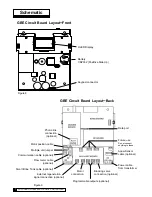
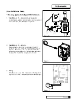
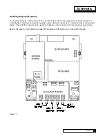

GbE Circuit board Layout
–
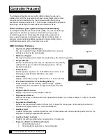
Front
Keypad connector
Battery
CR2032 (Postitive Side Up)
Schematic
OLED Display
Phone line
connection
(optional)
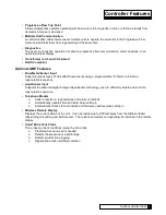
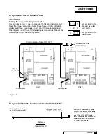
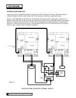
GbE Circuit board Layout
–
back
Figure 8
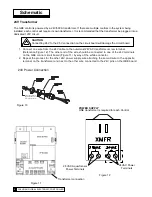
Motor position cable
Multiple unit jumper
Communication cable (optional)
Flow meter cable
(optional)
Smart Brine Tank cable (optional)
External regeneration
signal connection (optional)
Motor
connection
Programmable outputs (optional)
Blocking valve
connection (optional)
Power cable
from transformer
Aqua-Sensor
cable (optional)
Future use
Do not connect
anything to these
.
Data port
Figure 9
Schematic
8
7
CULLIGAN GLOBAL ELECTRONIC CONTROLLER
Содержание GBE
Страница 62: ...Menu Overview Continued on page 61 59 CULLIGAN GLOBAL ELECTRONIC CONTROLLER ...
Страница 63: ...Menu Overview Menu Overview 60 ...
Страница 64: ...Menu Overview Continued from page 59 61 CULLIGAN GLOBAL ELECTRONIC CONTROLLER ...
Страница 65: ...Menu Overview Menu Overview 62 ...
Страница 72: ...Appendix D 69 CULLIGAN GLOBAL ELECTRONIC CONTROLLER ...


