34
PC104 RocketPort Option
Testing a Comtrol Port
Testing a Comtrol
Port
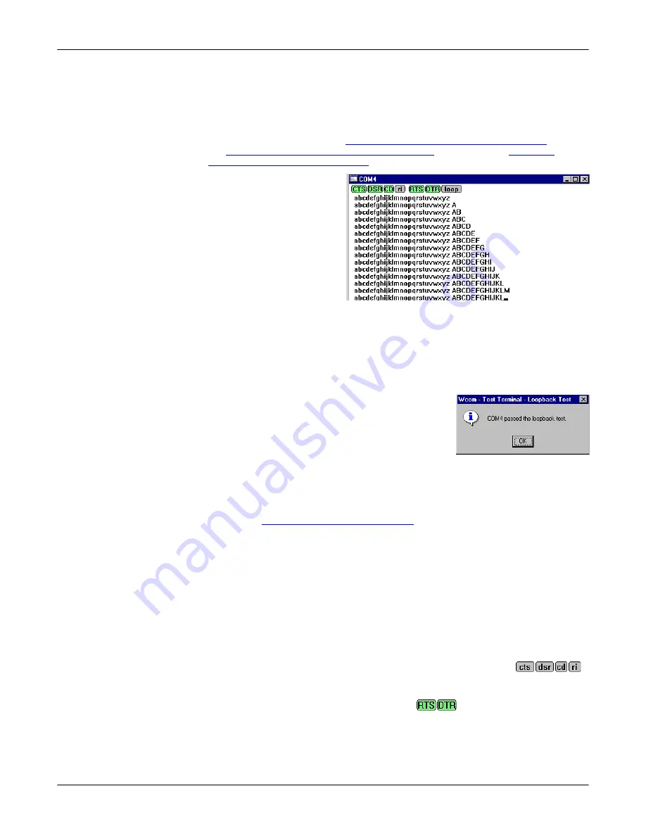
Use the following procedure to test the RocketPort PC104 serial port.
1.
Place a loopback plug on the COM port you are testing. Make sure all
connectors are seated firmly and that the loop button is
off
.
Note:
Test terminal works for RS-232 and RS-422 mode.
To build loopback plugs, see
Building Additional DB9 Loopback Plugs
Building Additional DB25 Loopback Plugs
on Page 31, or
Additional RJ45 Loopback Plugs
2.
From the
Port
menu, select
Send Test Data
. The
program sends out a
repeating data stream.
Note:
To stop the data
stream, select
Send
Test Data
again.
•
If the loopback plug is
in place and the port is
working correctly, the
test data should be
echoed back to the
screen.
•
If the loopback plug is
not
in place or the port is not working correctly, no
data or garbled data is echoed back to the screen.
Note:
If no characters appear, try putting the loopback plug on an adjacent
port. It may be that you have the ports mixed up.
3.
If further testing is required, select
Loopback Test
from the
Port
menu.
If the loopback plug is in place and the port is
working correctly, the system should return the
message
Passed
.
If the loopback plug is not in place or the port is
not working correctly, the system will return the
message
Failed
.
Testing an RS-485
Port
Perform the following procedure to determine if a port or ports are functioning
properly.
1.
Connect a straight-through cable from Port 1 to Port 2.
Note:
information. If testing ports other than Ports 1 and 2, connect the cable
between the two ports being tested.
2.
Open a session for each port.
3.
Enter data into the Port 1 session, the data should appear in the
Port 2
window.
4.
Enter data into the Port 2 session, the data should appear in the
Port 1
window.
Note:
If the data appears as described in Steps 3 and 4, the hardware is
functioning properly.
Test Terminal
Modem Control
Signals
The terminal window displays the modem control signals as gray
or green lights at the top of the window. The first four are inputs:
The lights are green if they are turned on, or gray if off. The text
on the light also changes from uppercase (CTS), which is on, to lowercase (cts),
which is off. The next two lights are outputs:
Note:
If you have a loopback plug connected and you click on one of the outputs,
the corresponding signal is sent to the input and the input lights should
toggle accordingly.
Содержание DeviceMaster ATS-XPE
Страница 1: ...Installation and Configuration Guide ...
Страница 24: ...24 Managing Files on the ATS XPE Using Remote Desktop through a Modem 6 Select the Connect button ...
Страница 76: ...76 Important Safety Information This page was intentionally left blank for double sided printing ...
Страница 78: ...78 Appendix C Default System Values Accessing the Motherboard ...
Страница 96: ...96 Index Index ...


