


en03d141.fm, 11.03.2008
PL12EN-1300 2008-03
55
Programming
3
3.5
RUN Screen
c0
02
89e
n
.b
m
p
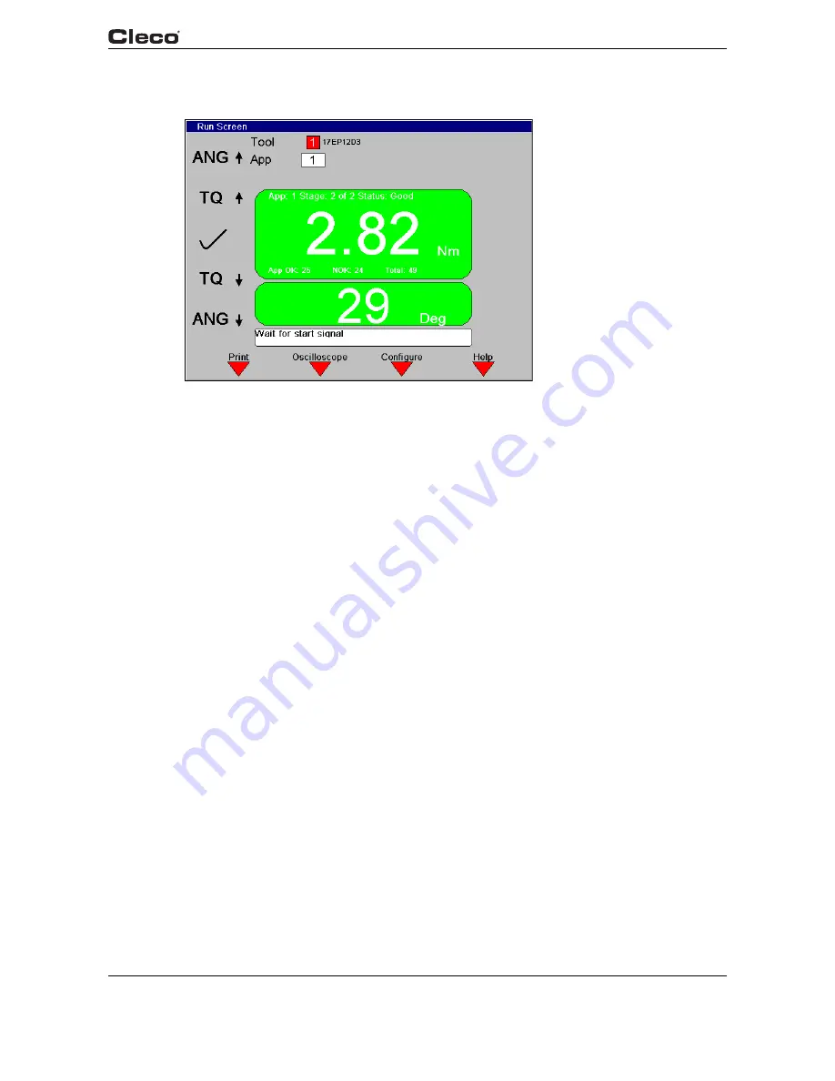
Fig. 3-20: Run Screen
runscrn.txtS
From the Run Screen the user sees rundown data as it occurs. The Torque and Angle readings
are displayed with a background color corresponding to the status of each.
The background is red if the value is too high, yellow if it is too low, and green if it is within limits.
The current tool model number, station name, and indicator labels are also displayed. The
desired Application (1-255), Tightening Group (1-8, if enabled), and Part ID (if enabled) are
selectable using the keypad.
When enabled, the Part ID and Part ID Status boxes are displayed below the Tool and Applica-
tion. When allowed, the Part ID edit box may be used to manually enter a Part ID using the key-
pad or an attached keyboard. NOTE: when manually entering a Part ID, the <ENTER> key must
be pressed to validate the entry. During manual entry, the <ESC> key may be pressed to return
to the previous Part ID and state of validity.
The Part ID Status box contains three indicators:
1.
Valid: Indicates whether or not the part ID is valid, and when not valid, whether or not the
tool is enabled:
- “Part ID Valid” (green LED): Part ID is valid. The tool is always enabled.
- “Part ID Invalid; Tool Disabled” (red LED): When configured in INTERLOCK mode, an
invalid Part ID causes the tool to be disabled. A new, valid Part ID must be entered to
enable the tool.
- “Part ID Invalid; Tool Enabled” (yellow LED): When configured without INTERLOCK mode,
the tool may be run without entering a valid Part ID.