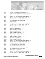
T A B L E S
xix
Cisco MGX 8850 Routing Switch Command Reference
Release 2.0, Part Number 78-10467-04 Rev C0, October 2001
Table 1
MGX 8850 Switch Release 2 Related Documentation
xxiii
Table 2
WAN CiscoView for MGX 8850 Release 2 Related Documentation
xxiii
Table 3
Cisco WAN Manager Release 10 Related Documentation
xxiv
Table 1-1
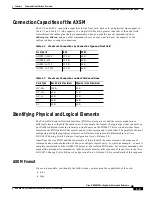
Valid Line Numbers and Number of Bays for AXSM Card Types
1 - 4
Table 1-2
Maximum Connections by Connection Type and Front Card
1 - 5
Table 1-3
Maximum Connections on Back Cards and Lines
1 - 5
Table 1-4
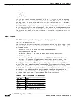
Mapping PNNI Port ID to AXSM Elements
1 - 6
Table 1-5
Commands
1 - 7
Table 2-1
Valid Line Numbers and Number of Bays for AXSM Card Types
2 - 2
Table 2-2
Maximum Connections by Connection Type and Front Card
2 - 3
Table 2-3
Maximum Connections on Back Cards and Lines
2 - 3
Table 2-4
Mapping PNNI Port ID to AXSM Elements
2 - 4
Table 2-5
Single-Card Upgrade From 2.x to 2.y
2 - 6
Table 2-6
Redundant Pair Upgrade From 2.x to 2.y
2 - 7
Table 2-7
Single-Card Upgrade From 2.x to 2.y
2 - 39
Table 2-8
Redundant Pair Upgrade From 2.x to 2.y
2 - 40
Table 2-9
Reasons for Change of Clock State
2 - 52
Table 2-10
Single-Card Upgrade From 2.x to 2.y
2 - 75
Table 2-11
Redundant Pair Upgrade From 2.x to 2.y
2 - 76
Table 2-12
Single-Card Upgrade From 2.x to 2.y
2 - 83
Table 2-13
Redundant Pair Upgrade From 2.x to 2.y
2 - 84
Table 3-1
Valid Line Numbers and Number of Bays for AXSM Card Types
3 - 2
Table 3-2
Maximum Connections by Connection Type and Front Card
3 - 3
Table 3-3
Maximum Connections on Back Cards and Lines
3 - 3
Table 3-4
Mapping PNNI Port ID to AXSM Elements
3 - 4
Table 4-1
Mapping PNNI Port ID to AXSM Elements
4 - 3
Table 5-1
Valid Line Numbers and Number of Bays for AXSM Card Types
5 - 4
Table 5-2
Mapping PNNI Port ID to AXSM Elements
5 - 5
Table 5-3
Routing Criteria and Service Classes
5 - 87
Table 6-1
Valid Line Numbers and Number of Bays for AXSM Card Types
6 - 3
Table 6-2
Maximum Connections by Connection Type and Front Card
6 - 3


