5-78
Cisco MGX 8850 Routing Switch Command Reference
Release 2.0, Part Number 78-10467-04 Rev C0, October 2001
Chapter 5
PNNI Commands
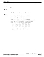
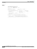
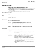
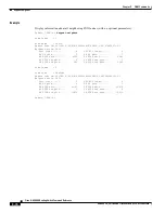
dsppnni-node
Display Contents
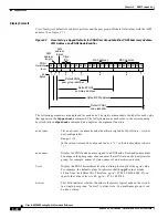
Cisco factory-set defaults for address prefixes and the peer group ID share field-values with the ATM
address. (See
Figure 5-7
.)
Figure 5-7
Cisco Factory-shipped Defaults for PNNI Peer Group Identifier, PNNI Summary Address,
ATM Address, and PNNI Node Identifier
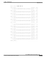
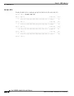
The following parameters are displayed for each node. The right column shows the label for each value
that appears in the dsppnni-node command. The left column maps each value to the corresponding
keyword in the cnfpnni-node command, and explains the argument function.
47
1
1
1
# of
Bytes
2
1
Default PNNI
peer group identifier
1
3
6
6
ATM
address
format
00
56 160
91 81 00 00 00 XX XX XX XX XX XX XX XX XX XX XX XX 00
53346
Cisco
ICD
MAC address
MAC address
ATM
address
length
PNNI
hierarchy
level
Default PNNI
summary address
Default ATM address
Default PNNI
node identifier
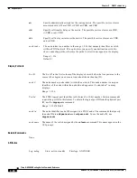
node index The
node-index is a numeric node identifier assigned by the software—it is not
user-configurable.
Range: 1–10
In the current release, the only node-index is “1,” so the display always shows
“1.”
node name
Display the PNNI node name assigned to a PNNI node. Each node name must
be unique in the peer group–choose names that all fit into an obviously similar
group, for example: names of states, names of universities, and such.
Level
Display the PNNI hierarchical level by defining the length of the pg-id value.
For example, the default values 56 indicates that the pgId value extends
56 bits from the leftmost bit. Therefore, pg-id = 47 01 00 8100 0000. If you
specify the value of level to 40, pg-id = 47 01 00 8100.
Lowest
This field indicates whether the node is the lowest logical node on the switch.
In a single-peer group, “Lowest” is always true. In a multi-peer group, it can
be true or false.


