5-28
Cisco MGX 8850 Routing Switch Command Reference
Release 2.0, Part Number 78-10467-04 Rev C0, October 2001
Chapter 5
PNNI Commands
cnfpnni-node
Cards on Which This Command Runs
PXM45
Syntax
cnfpnni-node <node-index>
[-atmAddr atm-address]
[-level level]
[-nodeId node-id]
[-pgId pg-id]
[-lowest {true | false}]
[-enable {true | false}]
[-transitRestricted {on | off}]
[-complexNode{on | off}]
[-branchingRestricted {on | off}]
Syntax Description
node-index
The node index specifies the relative position of a logical node within the
hierarchy of a multi-peer group. The lowest level is 1. In the current release,
the only node-index is ‘1’. Each new logical node added to the hierarchy
automatically gets the next higher index number, so you cannot configure the
node index.
Range: 1–10
Default: 1
-atmAddr
Specify the ATM address for this logical node. For you to change the ATM
address, the node must be disabled. For details, see the section, “
Disabling a
Node When Required
.” Note that only the lowest node in the hierarchy
requires an ATM address.
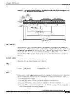
Default:
Figure 5-6
shows the factory-set default.
-level
This parameter specifies the level of the node within the PNNI hierarchy.
The level of the node is the number of bits in the node ID (-nodeId
parameter) or peer group ID (-pg-id parameter). For example, the default
level of 56 means that the node ID is 56 bits long. If you specify a level of
48, the node ID has a length of 48 bits.
The maximum number of levels you can configure on a switch 10. This limit
is meaningful in a multi-peer group only. Although the level can be any value
within the 1–104 range, selecting an 8-bit boundary makes network planning
and address management easier. Four example, using 56 for a level is more
expedient than using a level of 59.
Range: 1–104 bits
Default: 56 bits


