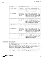
Side-by-side Redundancy for the XGLC
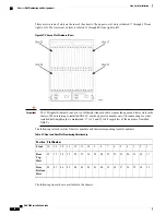
The XGLC is a full-height card that requires both top and bottom line card slots for a single 10-Gigabit port.
To achieve one-to-one line card redundancy, you must install two XGLCs in adjacent slots. Otherwise, you
configure port and card redundancy for the XGLCs in the same way as other line cards. There are no restrictions
that prevent the side-to-side 1:1 XGLC redundant arrangement from functioning with other Ethernet line card
types.
An active packet processing card must always be installed behind an XGLC. Monitoring functions occur in
a distributed fashion. Select the XGLCs that act as a redundant pair via the CLI. Configure the redundant pairs
prior to configuring the interface bindings so that proper parallel physical and logical port configurations are
established. The card redundancy and monitoring begins as soon as the packet processing card in front is
active.
The packet processing cards behind a pair of redundant XGLCs must always be in Active mode.
Important
Requirement Summary
There must be a direct connection to a packet processing card behind each side-by-side redundant XGLC pair.
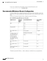
Configure the XGLC Ethernet line cards in a chassis as redundant pairs with cards in the following adjacent
slots:
•
17
–
18
•
19
–
20
•
21
–
22
•
23
–
26 (SPIOs 24 and 25 are skipped in this line card redundancy model)
•
27
–
28
•
29
–
30
•
31
–
32
Use only the top line card slot numbers to configure XGLC 1:1 redundancy.
Important
CLI Commands for XGLC Redundancy
Side-by-side 1:1 redundancy only operates on top line card slot numbers: cards 17 through 23 and 26 through
32. Make sure that both packet processing cards in front of the line cards are of the same type, configured as
a redundant pair, and active.The CLI configuration to support this redundancy mode is specified at the card
level as follows:
[local]asr5000#
config
[local]asr5000(config)#
card 17
[local]asr5000(config-card-17)#
redundant with 18
ASR 5000 Installation Guide
77
Line Card Installation
Side-by-side Redundancy for the XGLC
Содержание ASR 5000
Страница 16: ...ASR 5000 Installation Guide xvi About this Guide Contacting Customer Support ...
Страница 64: ...ASR 5000 Installation Guide 48 Installation Procedure Overview Laser Notice ...
Страница 100: ...ASR 5000 Installation Guide 84 Line Card Installation Installing the XGLC ...
Страница 118: ...ASR 5000 Installation Guide 102 Cabling the Switch Processor Input Output Line Card Central Office Alarm Wiring Example ...
Страница 122: ...ASR 5000 Installation Guide 106 Cabling the Fast Ethernet 10 100 Line Card FLC2 Interfaces ...
Страница 136: ...ASR 5000 Installation Guide 120 Cabling the Optical ATM Line Cards Cabling the Optical SFP Interface ...
Страница 140: ...ASR 5000 Installation Guide 124 Cabling the Channelized Line Cards Cabling the Optical SFP Interface ...
Страница 144: ...Figure 49 PFU Wiring Diagram ASR 5000 Installation Guide 128 Cabling the Power Filter Units Power Cable Requirements ...
Страница 148: ...ASR 5000 Installation Guide 132 Cabling the Power Filter Units Connecting the PFU to the Power Source ...
Страница 206: ...ASR 5000 Installation Guide 190 Removing and Installing SMC PC Cards Removing PC Cards ...
Страница 212: ...ASR 5000 Installation Guide 196 Replacing the Chassis Air Filter Installing the Air Filter ...
Страница 220: ...ASR 5000 Installation Guide 204 Replacing a Power Filter Unit What to do with the Failed PFU ...
Страница 266: ...ASR 5000 Installation Guide 250 Safety Electrical and EMC Certifications Korean EMC ...
Страница 270: ...ASR 5000 Installation Guide 254 Environmental Specifications Chassis Air Flow ...
Страница 280: ...ASR 5000 Installation Guide 264 Preparing a Full Height Line Card Slot Remove the Half Height Card Guide ...
Страница 294: ...ASR 5000 Installation Guide 278 Spare Component Recommendations Spare Component Recommendations ...

