Description
Item
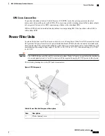
VDC (-48 VDC input terminals)
2
RTN (voltage return terminals)
3
PFU handle
4
Circuit breaker (On/Off) rated at 165A
5
Power LED
6
Fan Tray Assemblies
There are two fan tray assemblies within the chassis. A lower fan tray intakes ambient air and an upper fan
tray exhausts warmed air from the chassis. Each fan tray is connected to both PFUs to ensure power feed
redundancy. Both fan tray assemblies are variable speed units that automatically adjust fan speed based on
temperature or failover situations.
Thermal sensors monitor temperatures within the chassis. In the event of a fan failure or other
temperature-related condition, the SMC notifies all operable fans in the system to switch to high speed, and
generates an alarm.
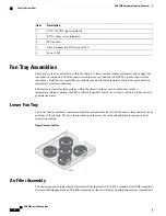
Lower Fan Tray
The lower fan tray assembly contains multiple fans and pulls ambient air into the chassis from the lower front
and sides of the chassis. The air is then pushed upward across the cards and midplane to support vertical
convection cooling.
Figure 7: Lower Fan Tray
Air Filter Assembly
The chassis supports a replaceable particulate air filter that meets UL 94-HF-1 standards for NEBS-compliant
electronics filtering applications. This filter mounts above the lower fan tray assembly and removes contaminants
ASR 5000 Installation Guide
12
ASR 5000 Hardware Platform Overview
Fan Tray Assemblies
Содержание ASR 5000
Страница 16: ...ASR 5000 Installation Guide xvi About this Guide Contacting Customer Support ...
Страница 64: ...ASR 5000 Installation Guide 48 Installation Procedure Overview Laser Notice ...
Страница 100: ...ASR 5000 Installation Guide 84 Line Card Installation Installing the XGLC ...
Страница 118: ...ASR 5000 Installation Guide 102 Cabling the Switch Processor Input Output Line Card Central Office Alarm Wiring Example ...
Страница 122: ...ASR 5000 Installation Guide 106 Cabling the Fast Ethernet 10 100 Line Card FLC2 Interfaces ...
Страница 136: ...ASR 5000 Installation Guide 120 Cabling the Optical ATM Line Cards Cabling the Optical SFP Interface ...
Страница 140: ...ASR 5000 Installation Guide 124 Cabling the Channelized Line Cards Cabling the Optical SFP Interface ...
Страница 144: ...Figure 49 PFU Wiring Diagram ASR 5000 Installation Guide 128 Cabling the Power Filter Units Power Cable Requirements ...
Страница 148: ...ASR 5000 Installation Guide 132 Cabling the Power Filter Units Connecting the PFU to the Power Source ...
Страница 206: ...ASR 5000 Installation Guide 190 Removing and Installing SMC PC Cards Removing PC Cards ...
Страница 212: ...ASR 5000 Installation Guide 196 Replacing the Chassis Air Filter Installing the Air Filter ...
Страница 220: ...ASR 5000 Installation Guide 204 Replacing a Power Filter Unit What to do with the Failed PFU ...
Страница 266: ...ASR 5000 Installation Guide 250 Safety Electrical and EMC Certifications Korean EMC ...
Страница 270: ...ASR 5000 Installation Guide 254 Environmental Specifications Chassis Air Flow ...
Страница 280: ...ASR 5000 Installation Guide 264 Preparing a Full Height Line Card Slot Remove the Half Height Card Guide ...
Страница 294: ...ASR 5000 Installation Guide 278 Spare Component Recommendations Spare Component Recommendations ...

