C H A P T E R
10
Cabling the Channelized Line Cards
This chapter provides information about the physical interfaces and instructions for installing the cables on
the CLC2 (STM-1/OC-3).
This chapter includes the following sections:
•
Channelized Line Card Interfaces, page 121
•
Cabling the Optical SFP Interface, page 123
Channelized Line Card Interfaces
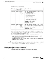
The CLC2 card supports two types of Small Form-factor Pluggable (SFP) transceiver modules. The type of
optical fiber interface on the line card is dictated by the SFP modules installed on the card. The SFP modules
are hot-pluggable.
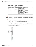
Table 45: SFP Modules Supported by the CLC2
Cable Specifications
Interface
Type
Card
Identification
Module Type
Fiber Types:
Single-mode optical fiber
Wavelength:
1310 nm
Core Size:
9 micrometers
Cladding Diameter:
125 micrometers
Range:
Intermediate/21 kilometers
Attenuation:
0.25 dB/KM
Min/Max Tx Power:
-15 dBm/-8 dBm
Rx Sensitivity:
-28 dBm
Single-mode
Fiber, LC
duplex
female
connector
Channelized
(STM-1/OC-3)
SM IR-1
Single-mode
Optical Fiber
ASR 5000 Installation Guide
121
Содержание ASR 5000
Страница 16: ...ASR 5000 Installation Guide xvi About this Guide Contacting Customer Support ...
Страница 64: ...ASR 5000 Installation Guide 48 Installation Procedure Overview Laser Notice ...
Страница 100: ...ASR 5000 Installation Guide 84 Line Card Installation Installing the XGLC ...
Страница 118: ...ASR 5000 Installation Guide 102 Cabling the Switch Processor Input Output Line Card Central Office Alarm Wiring Example ...
Страница 122: ...ASR 5000 Installation Guide 106 Cabling the Fast Ethernet 10 100 Line Card FLC2 Interfaces ...
Страница 136: ...ASR 5000 Installation Guide 120 Cabling the Optical ATM Line Cards Cabling the Optical SFP Interface ...
Страница 140: ...ASR 5000 Installation Guide 124 Cabling the Channelized Line Cards Cabling the Optical SFP Interface ...
Страница 144: ...Figure 49 PFU Wiring Diagram ASR 5000 Installation Guide 128 Cabling the Power Filter Units Power Cable Requirements ...
Страница 148: ...ASR 5000 Installation Guide 132 Cabling the Power Filter Units Connecting the PFU to the Power Source ...
Страница 206: ...ASR 5000 Installation Guide 190 Removing and Installing SMC PC Cards Removing PC Cards ...
Страница 212: ...ASR 5000 Installation Guide 196 Replacing the Chassis Air Filter Installing the Air Filter ...
Страница 220: ...ASR 5000 Installation Guide 204 Replacing a Power Filter Unit What to do with the Failed PFU ...
Страница 266: ...ASR 5000 Installation Guide 250 Safety Electrical and EMC Certifications Korean EMC ...
Страница 270: ...ASR 5000 Installation Guide 254 Environmental Specifications Chassis Air Flow ...
Страница 280: ...ASR 5000 Installation Guide 264 Preparing a Full Height Line Card Slot Remove the Half Height Card Guide ...
Страница 294: ...ASR 5000 Installation Guide 278 Spare Component Recommendations Spare Component Recommendations ...


