


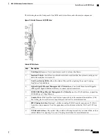


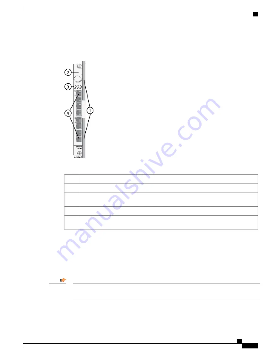
The following shows the panel of the FLC2 with its interfaces and major components.
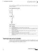
Figure 14: Fast Ethernet Line Card (FLC2)
Table 11: FLC2 Callouts
Description
Item
Card Ejector Levers
—
Use to insert/remove card to/from chassis.
1
Interlock Switch
—
In its Down position the interlock switch notifies the system to safely power
down the card prior to its removal.
2
Card Level Status LEDs
—
Show the status of the card.
3
RJ-45 10/100 Ethernet Interfaces
—
Eight auto-sensing RJ-45 interfaces for R-P interface
connectivity carrying user data. Ports are numbered 1 through 8 from top to bottom.
4
Gigabit Ethernet Line Card (GLC2)
The GLC2 installs directly behind its respective packet processing card, providing network connectivity to
the packet data network. The GLC2 (Ethernet 1000) supports a variety of 1000 Mbps optical and copper
interfaces based on the type of Small Form-factor Pluggable (SFP) modules installed on the card.
The GELC has reached its end of life and is no longer available for purchase. It has been replaced by the
GLC2.
Important
ASR 5000 Installation Guide
25
ASR 5000 Hardware Platform Overview
Gigabit Ethernet Line Card (GLC2)
Содержание ASR 5000
Страница 16: ...ASR 5000 Installation Guide xvi About this Guide Contacting Customer Support ...
Страница 64: ...ASR 5000 Installation Guide 48 Installation Procedure Overview Laser Notice ...
Страница 100: ...ASR 5000 Installation Guide 84 Line Card Installation Installing the XGLC ...
Страница 118: ...ASR 5000 Installation Guide 102 Cabling the Switch Processor Input Output Line Card Central Office Alarm Wiring Example ...
Страница 122: ...ASR 5000 Installation Guide 106 Cabling the Fast Ethernet 10 100 Line Card FLC2 Interfaces ...
Страница 136: ...ASR 5000 Installation Guide 120 Cabling the Optical ATM Line Cards Cabling the Optical SFP Interface ...
Страница 140: ...ASR 5000 Installation Guide 124 Cabling the Channelized Line Cards Cabling the Optical SFP Interface ...
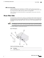
Страница 144: ...Figure 49 PFU Wiring Diagram ASR 5000 Installation Guide 128 Cabling the Power Filter Units Power Cable Requirements ...
Страница 148: ...ASR 5000 Installation Guide 132 Cabling the Power Filter Units Connecting the PFU to the Power Source ...
Страница 206: ...ASR 5000 Installation Guide 190 Removing and Installing SMC PC Cards Removing PC Cards ...
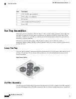
Страница 212: ...ASR 5000 Installation Guide 196 Replacing the Chassis Air Filter Installing the Air Filter ...
Страница 220: ...ASR 5000 Installation Guide 204 Replacing a Power Filter Unit What to do with the Failed PFU ...
Страница 266: ...ASR 5000 Installation Guide 250 Safety Electrical and EMC Certifications Korean EMC ...
Страница 270: ...ASR 5000 Installation Guide 254 Environmental Specifications Chassis Air Flow ...
Страница 280: ...ASR 5000 Installation Guide 264 Preparing a Full Height Line Card Slot Remove the Half Height Card Guide ...
Страница 294: ...ASR 5000 Installation Guide 278 Spare Component Recommendations Spare Component Recommendations ...