Electrical Characteristics
Each of the three dry-contact relay switches is rated to support a maximum switching current of 1A@30VDC.
The relay contacts should not directly connected to high current devices such as sirens and flashing lamps.
The CO alarm interface of the SPIO is suitable for connection to intra-building or unexposed wiring or
cabling only. This interface MUST NOT be metallically connected to interfaces that connect to the outside
plant (OSP) or its wiring. This interface is designed for use as an intra-building interface only (Type 2 or
Type 4 ports as described in GR-1089-CORE, Issue 5) and requires isolation from the exposed OSP
cabling. The addition of Primary Protectors is not sufficient protection in order to connect these interfaces
metallically to OSP wiring.
Important
Central Office Alarm Wiring Example
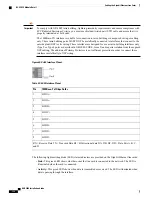
The following figure depicts how the dry-contact relays can each control up to two external alarm indicators.
In this example, the CO alarm interface is connected to a CO Alarm Panel, where green LEDs are wired to
indicate normal operation, and red LEDs are wired to indicate an alarm condition.
Figure 40: CO Alarm Interface Schematic
ASR 5000 Installation Guide
100
Cabling the Switch Processor Input/Output Line Card
Electrical Characteristics
Содержание ASR 5000
Страница 16: ...ASR 5000 Installation Guide xvi About this Guide Contacting Customer Support ...
Страница 64: ...ASR 5000 Installation Guide 48 Installation Procedure Overview Laser Notice ...
Страница 100: ...ASR 5000 Installation Guide 84 Line Card Installation Installing the XGLC ...
Страница 118: ...ASR 5000 Installation Guide 102 Cabling the Switch Processor Input Output Line Card Central Office Alarm Wiring Example ...
Страница 122: ...ASR 5000 Installation Guide 106 Cabling the Fast Ethernet 10 100 Line Card FLC2 Interfaces ...
Страница 136: ...ASR 5000 Installation Guide 120 Cabling the Optical ATM Line Cards Cabling the Optical SFP Interface ...
Страница 140: ...ASR 5000 Installation Guide 124 Cabling the Channelized Line Cards Cabling the Optical SFP Interface ...
Страница 144: ...Figure 49 PFU Wiring Diagram ASR 5000 Installation Guide 128 Cabling the Power Filter Units Power Cable Requirements ...
Страница 148: ...ASR 5000 Installation Guide 132 Cabling the Power Filter Units Connecting the PFU to the Power Source ...
Страница 206: ...ASR 5000 Installation Guide 190 Removing and Installing SMC PC Cards Removing PC Cards ...
Страница 212: ...ASR 5000 Installation Guide 196 Replacing the Chassis Air Filter Installing the Air Filter ...
Страница 220: ...ASR 5000 Installation Guide 204 Replacing a Power Filter Unit What to do with the Failed PFU ...
Страница 266: ...ASR 5000 Installation Guide 250 Safety Electrical and EMC Certifications Korean EMC ...
Страница 270: ...ASR 5000 Installation Guide 254 Environmental Specifications Chassis Air Flow ...
Страница 280: ...ASR 5000 Installation Guide 264 Preparing a Full Height Line Card Slot Remove the Half Height Card Guide ...
Страница 294: ...ASR 5000 Installation Guide 278 Spare Component Recommendations Spare Component Recommendations ...

